
 Portable EV Charger
 Home EV Wallbox
 DC Charger Station
 BESS Charging Station
 V2G V2H V2V V2L
 EV Charging Module
 DC Charging Connector
 EV Accessories
Introduce Pantograph Up for Electric Bus Charger
Electric Bus Pantograph Up: Standard Operating Procedure (SOP)
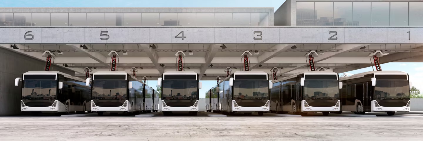
The “Pantograph Up” charging system is a fully automated, hands-free solution. Drivers are not required to exit the vehicle or handle high-voltage cabling. Operations are conducted entirely from the cockpit via the onboard interface.
1. Precision Docking & Stationary Protocol
- Alignment: Approach the charging bay at low speed. Utilize ground markings or the overhead laser/camera docking guides located on the charging mast to align the vehicle.
- Positioning: Bring the bus to a full stop directly beneath the overhead charging hood. The typical docking tolerance is ±30 cm longitudinally (forward/backward) and ±10 cm laterally (sideways).
- Safety Interlock: Shift the transmission to Neutral (N) and engage the Parking Brake.
- Note: The charging system is interlocked with the vehicle’s braking system; deployment will be inhibited if the parking brake is not set or the vehicle remains in gear.
2. Deployment & Connection Initiation
- Wireless Handshake: Once the vehicle is stationary, the bus automatically establishes a secure communication link (Wi-Fi or RFID) with the charging infrastructure.
- Initiation: Activate the “Start Charge” or “Pantograph Up” command via the dashboard console or touchscreen.
- Status Monitoring: Monitor the instrument cluster for live feedback (e.g., “Pantograph Deploying”). The mechanical arm will unfold and extend to the overhead contact rails.
- Engagement: The carbon contact strips will seat firmly into the overhead hood, completing the high-power circuit.
3. Charging Management
- BMS Integration: The Battery Management System (BMS) performs a diagnostic handshake with the charger to synchronize voltage and current parameters.
- Power Transfer: High-capacity DC charging (typically 150kW to 600kW) commences automatically.
- Drive-Off Interlock: An active safety lockout remains in effect during charging. The vehicle’s traction system is disabled, preventing the bus from moving even if the accelerator is depressed, thereby protecting the overhead infrastructure.
4. Retraction & Departure
- Termination: Charging ceases automatically upon reaching the target State of Charge (SoC). To terminate early, select “Stop Charge” or “Pantograph Down” on the console.
- Stowage: The pantograph arm will retract and fold into its stowed position on the roof.
- Verification: Confirm the status indicator reads “Pantograph Stowed” or “Safe to Drive” before moving.
- Departure: Release the parking brake, select the appropriate gear, and exit the charging bay cautiously.
Operational Constraints & Safety Guidelines
- Infrastructure Clearance: Prior to deployment, verify that the path between the bus roof and the charging hood is clear of obstructions, such as low-hanging branches or debris.
- Mechanical Alerts: Do not attempt to move the vehicle if the dashboard indicates the pantograph is not fully seated in its stowed position.
- Environmental Factors: During extreme weather (freezing rain or ice storms), inspect the overhead rails for heavy ice accumulation. Excessive icing may impede the connection or cause electrical arcing.
Pantograph Charging Technology: A Core Solution for Electrification in High-Intensity Commercial Transportation
I. Technology Definition and Core Principles
Pantograph charging is an automated, high-power conductive charging solution designed specifically for electric buses (e-Buses) and heavy-duty commercial vehicles.
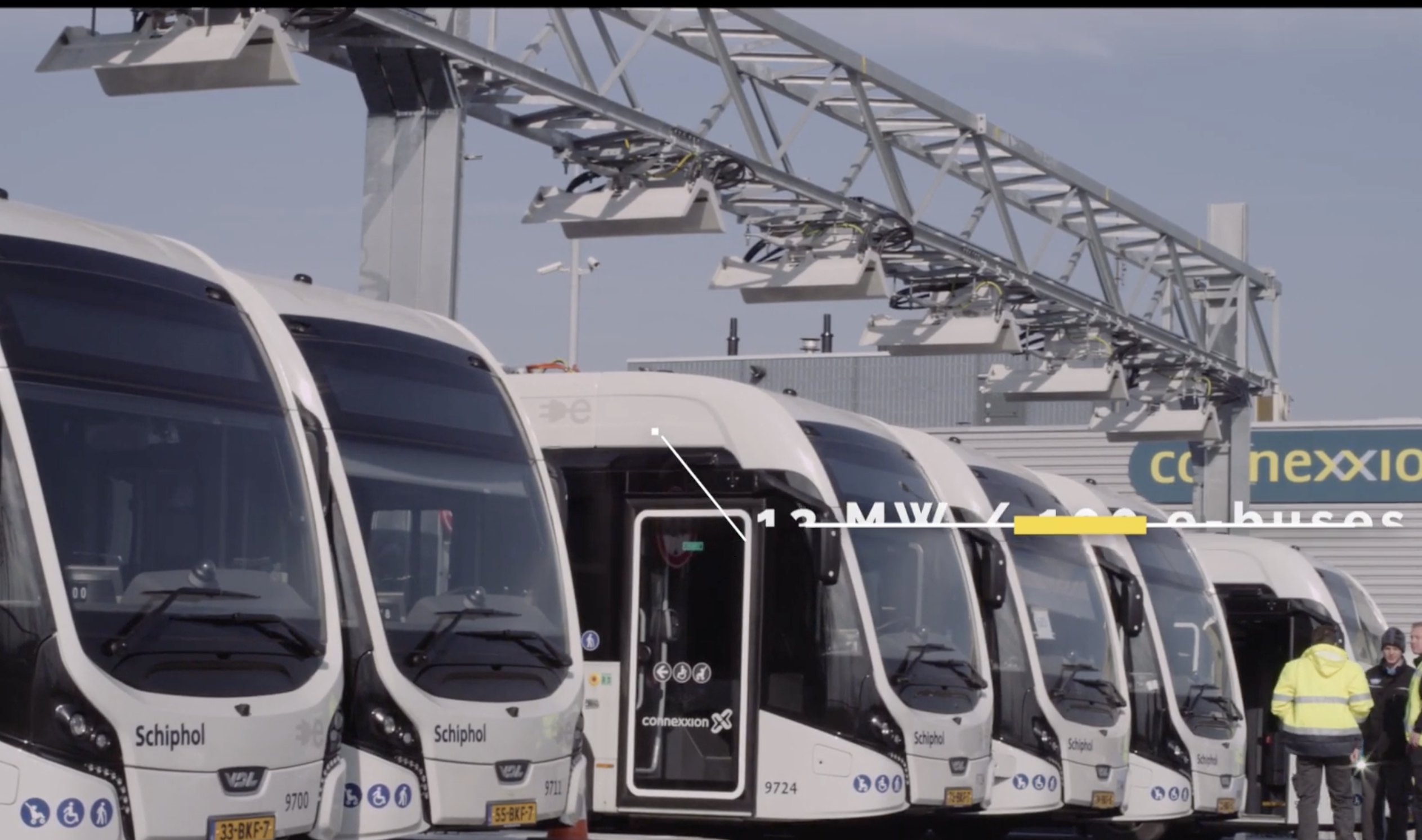
This system eliminates the traditional manual charging gun method. An automated robotic arm (the pantograph), mounted on a rooftop or ground-mounted support, establishes physical contact with a power rail on the vehicle’s roof, enabling rapid transmission of high-voltage direct current.
Physical Architecture: Consists of the robotic arm, carbon brush/copper busbar contacts, rooftop rails, and alignment sensors.
Energy Transfer: Supports ultra-high power charging from 150 kW to 600 kW, with some advanced systems evolving towards megawatt-level (MCS standard).
II. Operation Modes: Depot Charging vs. Opportunity Charging
Based on fleet operation logic, pantograph charging is mainly divided into two strategic deployment modes:
Mode | Application Scenarios | Technical Characteristics | Strategic Benefits
Depot Charging: When vehicles return to hub stations, park overnight, or during shift changes. 300kW-600kW, intelligent one-to-many dispatch capability. Reduces peak power demand and alleviates pressure on depot power distribution.
Opportunity Charging: At route terminus, major passenger hubs, or short-term stops. 150kW-450kW, ultra-short charge of 5-20 minutes. Achieves “small battery + long range,” reducing vehicle weight and increasing passenger capacity.
III. Infrastructure and Installation Requirements
Successful deployment of the pantograph system involves complex civil engineering and power system integration:
Structural Support: Requires the construction of precisely engineered steel structure booms or gantry frames, coupled with reinforced concrete foundations to withstand vibrations generated by the robotic arm’s movement.
Power Supply: A dedicated transformer and medium-to-high voltage switchgear are required to support instantaneous peak loads.
Alignment Assistance: An integrated roadside curb guidance system or infrared/ultrasonic automatic alignment assistance ensures that the contact error between the pantograph and the guide rail is controlled within centimeters.
Environmental Protection: An all-weather enclosure designed for harsh outdoor climates (rain, snow, strong winds, corrosion).
IV. Core Advantages Analysis
* Extreme Operational Turnover Rate: Automatic docking and disconnection completely eliminates the time loss associated with manual cable connection, achieving seamless “stop and charge”.
Lightweight Vehicle: Frequent high-power charging eliminates the need for a bulky long-range battery pack, significantly improving energy efficiency.
Personnel Safety: The entire charging process requires no driver contact with high-voltage equipment, completely avoiding the risk of electric shock and ergonomic injuries associated with manual operation.
V. Industry Challenges and Limitations
Despite technological maturity, the following bottlenecks remain for large-scale deployment:
Capital Expenditure (CAPEX): The construction cost of pantograph stations is significantly higher than that of traditional charging piles, involving substantial municipal infrastructure modifications.
Compatibility and Standardization: Pantograph specifications (such as alignment height and communication protocols) from different manufacturers are not yet fully standardized, affecting interoperability across different brand fleets.
Space Occupancy: Installing large cantilever frames in older urban areas or space-constrained hubs may face space conflicts.
 VI. Applicable Users and Fields
This technology is not designed for private vehicles. Its core target audience includes:
Public Transportation: Fixed-route urban electric buses and Bus Rapid Transit (BRT) systems.
Ports and Logistics: Automated tractors and heavy trucks operating in enclosed dock areas and large warehousing centers.
Heavy Industry: Electric mining trucks with fixed transportation routes in mines, quarries, etc.
Post time: Jul-11-2026
