
 Portable EV Charger
 Home EV Wallbox
 DC Charger Station
 BESS Charging Station
 V2G V2H V2V V2L
 EV Charging Module
 DC Charging Connector
 EV Accessories
Comprehensive Technical Buyer’s Guide for 150kW DC Fast Charging Stations: Navigating Modular Power Architectures, Grid Integration, Thermal Management, Multi-Layer Protection Systems, OCPP Interoperability, and Scalable Revenue Models for Future-Proof EV Infrastructure
Chapter 1: Introduction: The Rise of 150kW DC Fast Charging in the Global EV Landscape
The global transition toward electric mobility is no longer a peripheral trend but a central pillar of international climate policy and industrial strategy. As internal combustion engine (ICE) bans loom in major markets and consumer adoption of electric vehicles (EVs) accelerates, the demand for robust, reliable, and high-speed charging infrastructure has reached a fever pitch. Within the spectrum of Electric Vehicle Supply Equipment (EVSE), the 150kW DC fast charger has emerged as a critical “sweet spot” for commercial operators, fleet managers, and public utility providers.
Unlike low-power AC chargers that are suitable for overnight residential use, or ultra-high-power 350kW+ chargers that are currently reserved for high-end luxury vehicles and long-haul trucking, the 150kW station offers a balanced proposition. It provides significantly faster turnaround times than 50kW units—often replenishing 80% of a modern EV battery in under 30 minutes—while maintaining a manageable footprint and grid requirement. This makes it the ideal candidate for highway service stations, retail hubs, and urban “fast-fill” environments.
However, choosing the right 150kW charger is not merely a matter of selecting a brand from a catalog. It involves a deep understanding of power electronics, cooling technologies, software protocols, and economic modeling. A poorly selected unit can lead to high maintenance costs, frequent downtime, and a rapid obsolescence as battery technologies evolve. This guide serves as a technical deep-dive into the world of 150kW DC fast charging, providing buyers with the knowledge needed to navigate the complexities of selection, installation, and long-term operation.
We will explore why modularity is the cornerstone of modern charger design, how advanced thermal management protects the lifespan of the equipment, and how integration with the Open Charge Point Protocol (OCPP) ensures that your investment remains flexible and interoperable. Furthermore, we will dissect the revenue models that make 150kW stations a viable business case, looking beyond simple kilowatt-hour sales to value-added services and grid support.
Chapter 2: Technical Selection: Defining the 150kW Threshold for Commercial and Public Use
When evaluating a 150kW DC fast charger, the first technical consideration is the actual delivery capacity at the vehicle interface. Not all “150kW” chargers are created equal. The rated power is often a theoretical maximum achieved only under specific voltage and current conditions. For a buyer, understanding the voltage range—typically 200V to 1000V—is crucial. Modern EVs, such as those built on 800V architectures (e.g., Porsche Taycan, Hyundai IONIQ 5, Kia EV6), require chargers that can sustain high voltage to reach their peak charging speeds. A charger limited to 500V will struggle to deliver 150kW to these newer vehicles, effectively bottlenecking the performance.
Another key aspect of selection is the “simultaneous charging” capability. Many 150kW stations are equipped with two connectors (CCS1, CCS2, or CHAdeMO). A high-quality station will feature dynamic power sharing. For instance, if two vehicles are plugged in, the station should be able to allocate 75kW to each, or intelligently prioritize the vehicle with the lower state of charge. Understanding the granularity of this power allocation—whether it happens in 10kW increments or fixed 50/50 splits—is a vital technical differentiator.
The physical footprint and enclosure rating also play a significant role. For urban installations where space is at a premium, a compact, all-in-one unit is often preferred. However, for highway sites, a split-architecture system (where the power conversion occurs in a remote cabinet and the user interacts with a slim dispenser) might be more appropriate. Buyers must also verify the Ingress Protection (IP) and Impact Protection (IK) ratings. For outdoor public use, an IP54 or IP55 rating combined with an IK10 rating for the housing and screen is generally considered the industry standard for durability against weather and vandalism.
Lastly, the user interface (UI) and payment integration cannot be overlooked. A 150kW charger is a public-facing piece of infrastructure. The technical selection must include a high-brightness, sunlight-readable touchscreen, multi-language support, and a robust payment terminal that supports RFID, credit/debit cards, and mobile wallets. In many jurisdictions, “open access” laws now mandate that chargers must accept credit cards without requiring a specific app or membership, making the choice of integrated payment hardware a regulatory necessity.
Chapter 3: The Power of Modularity: Architecture, Parallel Scaling, and Redundancy
In the early days of DC fast charging, many units were built using “monolithic” architectures. If a single internal component failed, the entire charger went offline. Today, the industry has shifted toward modular parallel architecture, which is arguably the most important technical advancement for 150kW chargers. In this design, the 150kW output is generated by a stack of smaller, hot-swappable power modules—typically 20kW, 30kW, or 40kW each.
The advantages of modularity are three-fold: reliability, serviceability, and scalability. From a reliability perspective, if a 150kW charger is composed of five 30kW modules and one module fails, the station does not go dark. Instead, it enters a “degraded mode,” continuing to offer 120kW of power to the user. This ensures that a driver is never stranded, which is critical for maintaining high customer satisfaction and site reputation.
Serviceability is also vastly improved. Instead of requiring a highly specialized engineer to diagnose and repair complex internal circuitry on-site, a technician can simply identify the faulty module and swap it for a new one in minutes. This reduces Mean Time to Repair (MTTR) and minimizes the logistical burden of stocking large, heavy spare parts. For large-scale operators, this translates to significantly lower operational expenditures (OPEX).
Finally, modularity provides a path for future-proofing. A buyer might start with a 150kW configuration but install a cabinet capable of housing up to 200kW or 300kW worth of modules. As demand grows and grid capacity allows, the operator can simply plug in additional modules to increase the site’s capacity without needing to replace the entire physical station or dig new trenches. This “pay-as-you-grow” model is highly attractive for investors who are uncertain about the immediate rate of EV adoption in their specific locale.
Chapter 4: Power Module Synergy: Efficiency Optimization and Load Balancing Algorithms
The intelligence of a 150kW DC fast charger lies not just in its raw power components, but in the sophisticated software that orchestrates the synergy between its constituent power modules. In a modular system, the central controller acts as the “brain,” managing how current is drawn from each module to maximize efficiency and longevity. This is achieved through advanced load balancing algorithms that monitor the real-time health, temperature, and usage history of every individual module in the stack.
Efficiency optimization is a critical factor for the economic viability of a charging station. Most power modules have an efficiency curve that peaks at a certain load—often between 50% and 80% of their rated capacity. If a 150kW charger is delivering only 30kW to a vehicle with a nearly full battery, running all modules at 20% load would be highly inefficient due to fixed switching losses and auxiliary power draw. A smart controller will instead hibernate four modules and run a single 30kW module at its peak efficiency point. This “sleep mode” functionality can save thousands of kilowatt-hours over the lifespan of a charger, directly impacting the operator’s bottom line.
Load balancing also extends to the thermal management of the modules. During high-power sessions, modules generate significant heat. A sophisticated algorithm will rotate the load among modules to ensure that no single unit is consistently running hotter than the others. By distributing the “thermal stress” evenly, the system prevents localized aging and extends the Mean Time Between Failures (MTBF) for the entire power stack. Furthermore, these algorithms can detect early signs of module degradation—such as unusual voltage ripples or excessive heat for a given load—and proactively flag them for maintenance before a failure occurs.
For multi-dispenser sites, the synergy becomes even more complex. A centralized power cabinet serving multiple pedestals must dynamically allocate its module resources based on the varying state-of-charge (SoC) curves of the connected vehicles. If one vehicle is in its “bulk charge” phase and can accept 150kW, while another is in the “tapering” phase accepting only 20kW, the system must seamlessly shift modules from one output to the other. This requires high-speed communication protocols (often based on CAN bus or industrial Ethernet) within the charger to ensure that power shifts happen in milliseconds without interrupting the charging session or triggering vehicle-side safety shutdowns.
Chapter 5: Advanced Thermal Management: Liquid vs. Forced Air Cooling for High-Power Rectifiers
As DC fast chargers push into the 150kW range and beyond, thermal management becomes the primary engineering challenge. Converting high-voltage AC from the grid into DC for the battery is not 100% efficient; the roughly 4% to 7% energy loss manifests entirely as heat. In a 150kW system, this means managing up to 10kW of heat dissipation—equivalent to several large space heaters running inside a sealed metal box. How this heat is handled directly determines the charger’s reliability, noise level, and maintenance requirements.
Forced air cooling is the traditional and most common method for 150kW units. It utilizes high-velocity industrial fans to pull ambient air through the power modules and across heat sinks. While cost-effective and relatively simple to maintain, air cooling has several drawbacks. First, it introduces environmental contaminants—dust, moisture, and salt air—into the sensitive internal electronics, necessitating high-quality, frequently changed filters. Second, at peak power, the fans can be extremely noisy, which can be an issue in residential areas or high-end retail environments. To mitigate this, some manufacturers use “variable speed drive” fans that only ramp up when necessary, but the fundamental limitation remains.
Liquid cooling is the “gold standard” for high-density power electronics, though it is more commonly found in 350kW+ ultra-fast chargers. However, some premium 150kW designs are beginning to adopt liquid-cooled modules or cold-plate technology. In these systems, a coolant (typically a water-glycol mixture) is circulated through the power modules, carrying heat away to a remote radiator. This allows for a completely sealed enclosure, protecting electronics from the elements and significantly reducing noise. For buyers in extreme climates—either very hot deserts or coastal areas with salty air—the higher upfront cost of a liquid-cooled or sealed-air-path system is often justified by reduced maintenance and longer equipment life.
Another critical thermal consideration at 150kW is the charging cable itself. Standard non-cooled cables are typically limited to 200 Amps due to heat buildup in the copper conductors. To deliver 150kW to a 400V vehicle, the system needs to push 375 Amps. This necessitates either a very thick, heavy, and difficult-to-handle cable, or the use of a liquid-cooled cable. A cooled cable uses a circulating fluid to keep the handle and wire cool, allowing for a thinner, more ergonomic design that can handle 400A or 500A. When selecting a 150kW charger, buyers must check if the unit includes cooled cables or if it uses “boost” modes that allow high current for short periods followed by thermal throttling.
Chapter 6: Grid Connection and Power Quality: Harmonics, Transformers, and Local Energy Storage
The installation of a 150kW DC fast charger is as much a civil engineering project as it is an electrical one. A single 150kW unit draws a significant amount of power from the local distribution grid—often more than a small office building or a dozen homes combined. This requires careful coordination with the local utility company to ensure the grid can handle the sudden, massive step-loads associated with fast charging.
Power quality is a major technical concern for utilities. Fast chargers are non-linear loads that use high-frequency switching, which can introduce “harmonics” into the grid. These harmonics can cause overheating in utility transformers and interference with other sensitive equipment on the same circuit. High-quality 150kW chargers must feature Active Power Factor Correction (PFC) and sophisticated filtering to keep Total Harmonic Distortion (THD) below 5%, meeting standards like IEEE 519. Buyers should look for certifications that guarantee the charger will not “pollute” the local power supply, as some utilities may refuse connection to units that lack proper filtering.
The physical infrastructure often requires a dedicated transformer to step down medium-voltage (e.g., 11kV or 33kV) power to the 480V or 400V AC required by the charger. This transformer must be sized not just for the nominal 150kW, but for the peak potential load and future expansion. Furthermore, the distance between the transformer and the charger is critical; long runs of low-voltage cable can result in significant voltage drops and energy losses, reducing the effective power delivered to the vehicle and increasing the operator’s electricity bill.
In areas with weak grids or high “demand charges” (penalties for high peak power usage), local energy storage is becoming a popular solution. By pairing a 150kW charger with a Battery Energy Storage System (BESS), operators can “buffer” the grid. The BESS charges slowly from the grid during off-peak hours and then discharges rapidly to support the 150kW demand when a vehicle plugs in. This “peak shaving” strategy can significantly reduce operational costs and allow for high-speed charging in locations where a direct grid upgrade would be prohibitively expensive. Integrating this into the technical selection requires a charger with a DC-link architecture that can easily accept inputs from both the grid and a stationary battery.
Chapter 7: Safety First: Multi-Layer Hardware and Software Protection Mechanisms
Safety in high-power DC charging is paramount, as a 150kW charger operates at voltages and currents that can be lethal if not properly managed. A professional-grade 150kW station incorporates multiple layers of protection, spanning from the physical connectors to the cloud-based management software. These mechanisms are designed to protect the user, the vehicle, the grid, and the charging equipment itself from faults.
The first layer is physical hardware protection. This includes Residual Current Devices (RCDs) of Type B, which can detect both AC and DC leakage currents. In the event of a ground fault, these devices can trip in milliseconds, isolating the charger from the power supply. Additionally, the charger must have surge protection devices (SPDs) to guard against lightning strikes or grid transients. Inside the cabinet, each power module should have its own fuse or circuit breaker to prevent a localized failure from cascading into a larger fire hazard. The charging cable itself contains temperature sensors in the connector head; if the pins get too hot due to a poor connection or high ambient temperatures, the system will automatically ramp down the power or terminate the session.
The second layer is communication-based safety. Modern DC charging relies on the ISO 15118 or DIN 70121 protocols for handshaking between the charger and the vehicle. Before a single watt of power is delivered, the two systems perform a self-test. The vehicle communicates its battery health, maximum allowable voltage, and peak current limits. The charger verifies its internal status and insulation resistance. Only after both parties confirm a “safe to proceed” status does the contactor close. Throughout the charging session, this communication heartbeat is maintained; if the connection is lost for even a few milliseconds, the session is immediately cut for safety.
The third layer is insulation monitoring. DC fast chargers operate in an “IT grid” configuration (isolated terra), meaning neither the positive nor negative DC lines are connected to the ground. An Insulation Monitoring Device (IMD) constantly measures the resistance between the DC bus and the chassis. If moisture ingress or cable wear causes the insulation to degrade below a certain threshold (typically measured in kilo-ohms), the IMD triggers an immediate shutdown. This is crucial for preventing “touch voltage” hazards where a user could receive a shock from the charger’s metal casing.
Finally, software-defined protection provides a redundant safeguard. The central controller monitors all sensor data—temperature, voltage, current, and fan speed—against a set of predefined safety envelopes. If any parameter drifts outside the safe zone, the software can initiate a controlled shutdown. For example, if the grid voltage drops too low (brownout), the software will gracefully stop the session to prevent damage to the power modules’ input stages. Advanced systems also feature “arc flash detection,” which uses light sensors to detect internal electrical arcs and trip the main breaker before a fire can start.
Chapter 8: Software Ecosystem: OCPP 1.6J/2.0.1 Integration, Billing, and Remote Management
A 150kW DC fast charger is not a standalone appliance; it is a networked device that must integrate into a complex software ecosystem. The industry standard for this communication is the Open Charge Point Protocol (OCPP). When selecting a charger, ensuring full compliance with OCPP 1.6J (JSON) is the absolute minimum requirement, while support for the newer OCPP 2.0.1 standard is highly recommended for future-proofing.
OCPP allows the charger (the “charge point”) to communicate with a central server (the “Charging Station Management System” or CSMS). This integration enables essential features such as remote monitoring, firmware updates, and billing. For a buyer, OCPP integration means “no vendor lock-in.” If you are unhappy with your software provider, you can switch to another one without needing to replace the physical hardware. This flexibility is vital for long-term operational resilience. A truly “open” charger will have its OCPP implementation certified by the Open Charge Alliance (OCA), ensuring that it can seamlessly talk to any compliant back-end.
Billing and monetization are handled through this software layer. The charger sends metered data to the CSMS, which then processes payments based on energy consumed (kWh), time spent (minutes), or a combination of both. In many markets, dynamic pricing is becoming a key strategy—charging more during peak demand hours and offering discounts when renewable energy production is high. Advanced 150kW chargers also support “Plug & Charge” (ISO 15118-2), where the vehicle identifies itself to the charger automatically, eliminating the need for RFID cards or mobile apps. This provides a “Tesla-like” seamless experience for the user and increases the throughput of the station.
Remote management and diagnostics are where the software ecosystem provides the most value. A 150kW station is a high-value asset, and downtime directly translates to lost revenue. A robust CSMS can provide real-time alerts for any faults, allowing operators to fix issues—such as a software hang or a tripped breaker—remotely without sending a technician to the site. Furthermore, remote firmware updates ensure that the charger can stay compatible with new EV models as they are released. As battery chemistries and charging curves evolve, the charger’s software needs to be updated to optimize performance and safety.
Chapter 9: Economic Analysis: Capex, Opex, and the 150kW Revenue Model (ROI)
Investing in a 150kW DC fast charger requires a clear understanding of the financial landscape. The Total Cost of Ownership (TCO) is divided into Capital Expenditure (CAPEX) and Operational Expenditure (OPEX), each of which must be meticulously planned to ensure a positive Return on Investment (ROI).
CAPEX includes the purchase price of the charger itself, which for a high-quality 150kW unit can range from $30,000 to $60,000 depending on features and build quality. However, the hardware cost is often only 40% to 50% of the total installation cost. Civil works—trenching, concrete pads, and protective bollards—can be significant, especially in urban environments. Electrical upgrades, including a new transformer and high-capacity switchgear, can add tens of thousands of dollars to the bill. Permitting and interconnection fees from the utility company must also be factored in. For many buyers, government grants and tax incentives are crucial for offsetting these initial costs, often covering 50% to 80% of the CAPEX in regions with aggressive electrification goals.
OPEX is the ongoing cost of keeping the station running. The largest component is typically the electricity cost, which includes not just the energy consumed but also “demand charges.” These are monthly fees based on the highest peak power draw (in kW) recorded at the site. A single 150kW session can trigger a high demand charge that wipes out the profit from dozens of smaller sessions. Managing this requires smart charging software or local battery storage as discussed in Chapter 6. Other OPEX items include the monthly subscription for the CSMS, cellular connectivity for the charger, and annual maintenance visits. A good rule of thumb is to budget 3% to 5% of the hardware cost for annual maintenance and repairs.
The revenue model for a 150kW station is evolving beyond simple energy sales. While the “margin per kWh” is the primary driver, successful operators are diversifying their income streams. Some offer “premium speed” pricing, where customers pay a higher rate for access to the 150kW charger compared to slower units. Others use the charging station as a “loss leader” to drive foot traffic to retail locations—increasing “dwell time” and secondary spend at cafes or stores. Additionally, as V2G (Vehicle-to-Grid) technology matures, 150kW stations could potentially earn revenue by providing frequency regulation and other ancillary services to the grid. To calculate ROI, operators must project utilization rates—the percentage of the day the charger is actually in use. A 150kW charger typically needs a utilization rate of 15% to 20% to break even within 3 to 5 years, assuming a reasonable spread between electricity buy and sell prices.
Chapter 10: Installation and Long-Term Operations & Maintenance (O&M) Strategies
The transition from a purchased asset to an operational 150kW DC fast charging station is a complex journey that requires meticulous planning and a long-term commitment to maintenance. Installation is not a “plug-and-play” event; it is a multi-disciplinary engineering project. The site selection phase must account for accessibility—ensuring that long-wheelbase EVs and vans can easily maneuver into the charging bay without blocking traffic. The physical orientation of the charger should minimize cable strain; a poorly placed unit leads to cables being dragged across the pavement, causing premature wear on the insulation and connector heads.
Civil engineering considerations are equally vital. The concrete foundation for a 150kW unit must be engineered to support the weight of the cabinet (which can exceed 500kg for modular units) and resist wind loads in exposed locations. Underground conduit runs must be sized for high-capacity copper or aluminum cables, with careful attention to bend radii to prevent insulation damage. In colder climates, heat tracing for the conduits or the base might be necessary to prevent frost heave from damaging the electrical connections. Lighting is another critical but often overlooked aspect; a well-lit station feels safer for users at night and helps the integrated cameras (if present) to capture clear footage for security and vandalism prevention.
Once the station is energized, the focus shifts to Operations and Maintenance (O&M). A proactive O&M strategy is what separates a profitable site from a liability. We categorize maintenance into three types: preventative, corrective, and predictive. Preventative maintenance involves scheduled site visits—typically every six months—to perform tasks such as cleaning or replacing air filters, checking the torque on electrical terminations (which can loosen over time due to thermal cycling), and inspecting the charging cables for nicks or cuts. We also recommend a periodic “deep clean” of the enclosure to remove the buildup of dust and pollutants that can impede heat dissipation.
Corrective maintenance is the response to an actual failure. Having a Service Level Agreement (SLA) with a local electrical contractor is essential for ensuring that critical issues are addressed within 24 to 48 hours. For modular 150kW chargers, corrective maintenance often involves simply swapping out a power module, but it can also include repairing a broken screen or replacing a damaged charging handle. Predictive maintenance is the most advanced form, utilizing the data generated by the charger to anticipate failures. By monitoring the internal temperature of a power module relative to its load, the software can predict an impending fan failure or a degrading capacitor. This allows for replacement during a scheduled visit, avoiding an unscheduled outage and the associated loss of revenue and customer trust.
Chapter 11: Compliance, Standards, and Future-Proofing for Megawatt Charging
Navigating the landscape of international standards and local regulations is one of the most challenging aspects of choosing a 150kW DC fast charger. Compliance is not just about safety; it is about interoperability and legal protection. In North America, UL (Underwriters Laboratories) certification is the gold standard, specifically UL 2202 for DC charging equipment and UL 2231 for personnel protection systems. In Europe and many other regions, CE marking and adherence to the IEC 61851 and IEC 62196 series of standards are mandatory.
Beyond basic electrical safety, buyers must consider metrology standards. In many jurisdictions, such as Germany with its “Eichrecht” law, the energy meter inside the charger must be legally certified and visible to the consumer, ensuring that they are charged exactly for what they receive. As more countries adopt similar consumer protection laws, choosing a charger with a pre-certified, high-precision DC meter is a crucial step in future-proofing your investment. Furthermore, cybersecurity is becoming a regulatory focus. Chargers are entry points into the grid and the service provider’s network; they must implement robust encryption (TLS 1.2 or higher), secure boot processes, and regular security patches to protect against hacking and data breaches.
Future-proofing also means looking ahead to the next generation of EV technology. While 150kW is currently “fast,” the industry is already moving toward 350kW and even Megawatt Charging Systems (MCS) for heavy trucks. A forward-thinking buyer will choose a 150kW platform that is “upgradable.” This can mean a cabinet with empty slots for more power modules, or a system designed for “parallel coupling,” where two 150kW units can be combined to deliver 300kW to a single vehicle if needed. Additionally, support for ISO 15118-20 (the latest version of the communication standard) will be necessary to enable advanced features like bi-directional charging (V2G/V2H) and more sophisticated grid integration.
Another aspect of future-proofing is environmental sustainability. The materials used in the charger’s construction—recyclable aluminum vs. painted steel, the type of coolant used in liquid systems—will increasingly impact the station’s “green” credentials. Some operators are already incorporating solar canopies over their 150kW chargers. This not only provides shade and rain protection for users but also generates clean energy that can be fed directly into the DC bus of the charger, reducing transmission losses and improving the overall efficiency of the site.
Chapter 12: Conclusion: Making the Strategic Investment in 150kW DC Infrastructure
Choosing a 150kW DC fast charger is a multi-dimensional decision that sits at the intersection of electrical engineering, software integration, and business strategy. Throughout this guide, we have explored the technical nuances that differentiate a high-quality, reliable station from a generic one. We have seen that modularity is the foundation of reliability, advanced thermal management is the key to longevity, and OCPP compliance is the gateway to flexibility.
The 150kW threshold represents a strategic choice. It is fast enough to satisfy the modern EV driver’s need for a quick “top-up,” yet it is more cost-effective and easier to deploy than ultra-fast 350kW systems. For the buyer, the success of this investment depends on looking beyond the initial purchase price. The true value lies in the Total Cost of Ownership—the ability of the charger to maintain high uptime, adapt to new vehicle models, and generate consistent revenue through smart energy management and value-added services.
As the EV landscape continues to evolve at a breakneck pace, the decisions made today will resonate for a decade or more. By prioritizing safety, efficiency, and scalability, and by partnering with reputable manufacturers who provide robust O&M support, investors can build a charging network that not only meets the needs of today’s drivers but also stands ready for the challenges of tomorrow. The transition to electric mobility is a marathon, not a sprint, and the 150kW DC fast charger is one of the most powerful tools in our arsenal to ensure that journey is successful.
Appendix A: Technical Checklist for 150kW DC Fast Charger RFP (Request for Proposal)
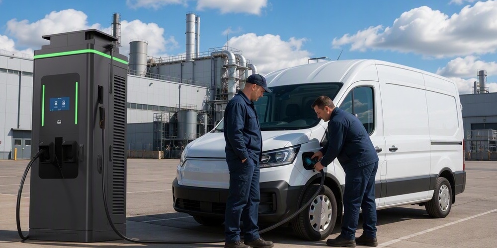
When issuing a Request for Proposal (RFP) for 150kW DC fast chargers, it is essential to be specific about your technical requirements to ensure you receive comparable and high-quality bids. Use the following checklist as a starting point:
- Power Architecture:
- Is the system modular? What is the power rating of each module?
- Does the system support hot-swapping of modules?
- What is the peak efficiency, and what is the efficiency curve at 25%, 50%, and 75% load?
- Output Specifications:
- What is the DC output voltage range (e.g., 200V – 1000V)?
- What is the maximum output current per connector?
- Does the station support dynamic power sharing between multiple connectors?
- Connectivity and Software:
- Is the charger fully OCPP 1.6J compliant? Is it OCPP 2.0.1 ready?
- What communication interfaces are supported (4G/5G, Ethernet, Wi-Fi)?
- Does the unit support ISO 15118 for Plug & Charge?
- Safety and Compliance:
- List all relevant certifications (UL, CE, IEC, etc.).
- What type of RCD and surge protection is included?
- Does the unit have integrated insulation monitoring (IMD)?
- Environmental and Physical:
- What are the IP and IK ratings of the enclosure?
- What is the operating temperature range (with and without derating)?
- What is the maximum noise level at full power (dB at 1 meter)?
- Cables and User Interface:
- What cable lengths are available? Are they liquid-cooled or air-cooled?
- Describe the touchscreen (size, brightness, multi-language support).
- What payment terminals are integrated (RFID, Credit Card, QR)?
- Maintenance and Support:
- What is the standard warranty period? What does it cover?
- Are spare parts (especially power modules) stocked locally?
- Does the manufacturer provide a cloud-based monitoring platform with remote diagnostics, OTA firmware updates, and fleet-level usage reporting?
- What is the OTA policy, and can a faulty firmware version be rolled back remotely?
- Can the platform export compliance-grade uptime and session logs for NEVI, AFIR, or utility audits?
- Power Modules and Serviceability:
- Is the power architecture modular (e.g., hot-swappable 30kW modules)?
- What is the mean time to repair (MTTR) for a module swap — 30 minutes or a technician visit?
- Are power modules shared across the vendor’s product line, so one spare-part pool covers 150kW, 350kW, and 480kW sites?
- Vendor Track Record:
- Request three reference sites within 500 km of your project and call the operators directly.
- Ask for published uptime statistics and a warranty-claims history — the numbers tell you more than any brochure.
- Future-Proofing:
- Can the dispenser be field-upgraded for NACS (J3400) without a full cabinet replacement?
- Is the platform ready for ISO 15118-20 bidirectional power (V2G)?
- Does the vendor have a documented MCS roadmap for heavy-duty charging?
Scoring and Selection Guidance
No single RFP item should decide the contract. Assign weights that mirror your business model: a highway corridor operator weights uptime and cold-weather performance; a fleet operator weights OCPP depth and spare-part logistics; a retail landlord weights payment integration and design flexibility. Score each vendor 1-5 per item, multiply by weight, and compare totals. A score above 4.0 signals a partner worth negotiating with; anything less means the “savings” will surface later as downtime, service calls, and stranded assets.
Two cautions when scoring: first, discount any vendor who cannot produce a certificate number, a test report, or a reference contact within one business day — documentation friction at the RFP stage reliably predicts service friction after commissioning. Second, separate “nice to have” from “must have” before you score, so a charismatic sales presentation does not inflate your weights. Finally, ask every shortlisted vendor for their five-year product roadmap in writing; the vendor whose roadmap includes NACS, V2G, and MCS is investing in the same future you are.
Closing: From Checklist to Contract
This appendix closes the guide the same way a good procurement process closes: with evidence. The 150kW segment is the workhorse of commercial charging, and the difference between a 10-year asset and a 3-year liability is decided in documents like this RFP. Modular architecture, honest compliance data, remote management, and a vendor roadmap that includes NACS and V2G are the markers of a strategic investment rather than a commodity purchase. Every item on this list is verifiable in a day of testing and a week of reference calls — if a vendor hesitates on any of them, the answer is already written.
Call to Action: Bid Your RFP to MIDA Power
MIDA Power’s 150kW modular chargers are built for this checklist: hot-swappable modules, OCPP 1.6J/2.0.1, ISO 15118 Plug & Charge, NACS-ready dispensers, and a cloud platform with compliance-grade reporting. Send us your RFP at sales@midapower.com — our bid team will respond with full specifications, certification files, reference contacts, and a total-cost-of-ownership model tailored to your site.
Post time: Aug-09-2026
