
 Portable EV Charger
 Home EV Wallbox
 DC Charger Station
 BESS Charging Station
 V2G V2H V2V V2L
 EV Charging Module
 DC Charging Connector
 EV Accessories
Technological Frontiers of Portable DC Charging Systems: A Deep Dive into High-Density Power Electronics, Modular Architecture, Multi-Standard Interoperability, and Strategic Deployment for Military, Emergency Relief, and Mobile Virtual Power Plant Integration
Chapter 1: Introduction: The Evolution of EV Infrastructure and the Crucial Need for Portability
The global transition toward electric mobility is no longer a peripheral trend but a central pillar of international climate policy and industrial strategy. As internal combustion engine (ICE) vehicles are phased out in favor of battery electric vehicles (BEVs), the focus has shifted from vehicle performance to the robustness and accessibility of the charging infrastructure. While stationary high-power charging (HPC) stations form the backbone of urban and highway networks, they are inherently limited by their geographical fixedness and reliance on heavy grid infrastructure. This limitation has catalyzed the development of a new class of energy assets: the Portable DC Charger.
A Portable DC Charger represents a fundamental shift in energy delivery. Unlike traditional Level 2 AC chargers that rely on the vehicle’s onboard converter—often limited to 7kW or 11kW—portable DC chargers bypass the onboard bottleneck by providing direct current directly to the battery pack. This allows for significantly higher power outputs (ranging from 20kW to 200kW+) in a form factor that can be moved, deployed, and redeployed within minutes. The engineering challenge lies in balancing the extreme power demands of DC fast charging with the physical constraints of mobility, weight, and environmental resilience.
The necessity for portable DC solutions arises from several critical use cases that stationary infrastructure cannot address. In automotive manufacturing and logistics, vehicles often need a rapid charge at specific points in the assembly line or shipping yard where installing permanent chargers is cost-prohibitive. In the service industry, emergency roadside assistance providers are replacing slow AC trickle-charging with mobile DC recovery units that can provide 20-30 miles of range in less than 10 minutes. Furthermore, as we look toward military and humanitarian applications, the ability to establish a high-power charging node in a “black start” or off-grid environment is becoming a matter of strategic importance.
This article provides an exhaustive technical exploration of the portable DC charging ecosystem. We will examine the intricate power electronics that enable high power density, the mechanical engineering required to withstand rigorous vibration and drop tests, and the software logic that allows a single unit to communicate across diverse global standards including NACS, CCS, and GBT. Finally, we will look toward the future, where these mobile assets are no longer just consumers of energy but active participants in the grid as mobile Virtual Power Plant (VPP) units.
Chapter 2: System Architecture: Modular Design and Convergent Power Path Engineering
The architecture of a portable DC charger is a study in spatial optimization and electromagnetic compatibility (EMC). A typical high-performance unit consists of four primary subsystems: the Power Conversion Stage, the Cooling System, the Control and Communication Module, and the Human-Machine Interface (HMI) with the associated Cable Management System.
2.1 The Modular Power Conversion Core
At the heart of the portable DC charger is the modular power block. Modern units utilize a “Lego-block” approach, where 20kW or 30kW power modules are stacked in parallel. This modularity serves two purposes. First, it provides redundancy; if one module fails, the system can continue to operate at a reduced capacity. Second, it allows manufacturers to scale the output of a portable unit based on customer needs without redesigning the entire chassis.
The power path begins with the AC input (typically 3-phase 400V/480V) entering through a ruggedized industrial connector. This AC power undergoes rectification and Power Factor Correction (PFC) to ensure that the charger does not introduce harmonic distortion into the source grid—a critical requirement for deployment in sensitive industrial or military environments. The corrected DC link then feeds a series of high-frequency isolated DC-DC converters, which step the voltage up or down to match the vehicle battery’s requirements (typically 200V to 1000V).
2.2 Control and Communication Architecture
The brain of the portable DC charger must be exceptionally versatile. Unlike a stationary charger that might only serve one region, a portable unit is often moved across borders or used to test diverse vehicle fleets. The control board must support multiple communication protocols:
- ISO 15118 / DIN 70121: For CCS1 and CCS2 communication.
- GB/T 27930: For the Chinese market and specific industrial applications.
- CHAdeMO: For legacy support and Japanese vehicle architectures.
- NACS (Tesla): The emerging North American standard.
This “Protocol Agnostic” approach requires a sophisticated gateway that can translate physical layer signals (like CAN bus for GB/T and CHAdeMO or HomePlug Green PHY for CCS) into a unified internal logic. This ensures that the safety checks—such as insulation monitoring and pre-charge sequences—are executed flawlessly regardless of the vehicle type.
2.3 Mechanical Integration and Form Factor
Designing a 60kW charger that fits in a suitcase or a small wheeled trolley requires extreme attention to “Power-to-Volume” ratios. Every cubic centimeter is contested. The layout must minimize the length of high-current busbars to reduce resistive heat and electromagnetic interference (EMI). Furthermore, the internal skeleton must be rigid enough to support heavy magnetic components while being light enough for manual handling. The use of advanced materials, such as aluminum alloys for the frame and high-impact polycarbonates for the shell, is standard in premium portable units.
Chapter 3: Power Conversion Topology: High-Frequency Magnetic Components and SiC/GaN Implementation
The transition from stationary to portable DC charging is fundamentally driven by the physics of power conversion. To reduce the size of the transformer—the largest component in any isolated power converter—one must increase the switching frequency. However, increasing frequency typically leads to higher switching losses in traditional Silicon (Si) MOSFETs and IGBTs. This is where Wide Bandgap (WBG) semiconductors, specifically Silicon Carbide (SiC) and Gallium Nitride (GaN), have revolutionized the industry.
3.1 The Role of Silicon Carbide (SiC) in Portable DC Systems
For portable chargers operating at power levels between 30kW and 200kW, SiC MOSFETs have become the gold standard. SiC offers a higher breakdown voltage, higher thermal conductivity, and significantly lower switching losses compared to Silicon. In a portable DC charger, this translates to a reduction in the size of the cooling fins and fans, as less energy is wasted as heat.
The primary topology used in these units is the Phase-Shifted Full-Bridge (PSFB) or the LLC Resonant Converter. The LLC converter is particularly favored for portable applications because it allows for Zero Voltage Switching (ZVS), which virtually eliminates turn-on losses. By operating at frequencies between 100kHz and 500kHz, the volume of the magnetic components can be reduced by up to 60% compared to traditional 20kHz designs.
3.2 High-Frequency Magnetic Design and Planar Transformers
The design of the magnetic components in a portable DC charger is an exercise in extreme engineering. At high frequencies, the “skin effect” and “proximity effect” cause current to flow only on the surface of the conductors, increasing resistance and heat. To combat this, portable chargers utilize Litz wire—consisting of thousands of individually insulated strands twisted together—or planar transformers.
Planar transformers replace traditional wire-wound coils with stacked copper layers on a Printed Circuit Board (PCB). This offers several advantages for portability:
- Low Profile: The height of the transformer is reduced, allowing for a thinner chassis.
- Superior Thermal Management: The flat surface area allows for direct contact with heat sinks or liquid-cooled plates.
- Repeatability: PCB manufacturing ensures that every transformer has identical parasitic capacitance and inductance, which is critical for the stability of LLC resonant circuits.
3.3 EMI and Noise Mitigation in Dense Environments
High-frequency switching inherently generates electromagnetic interference (EMI). In a compact portable unit, where control logic sits just millimeters away from high-power switching nodes, EMI mitigation is paramount. Engineers employ multi-stage LC filters at both the input and output stages. Furthermore, the use of “Soft-Switching” topologies helps reduce the $dv/dt$ and $di/dt$ rates, minimizing the high-frequency ringing that can interfere with the vehicle’s BMS communication or local radio signals.
Chapter 4: Energy Density Optimization: Thermal Management and Volumetric Efficiency
Energy density in the context of a portable DC charger is measured in kilowatts per kilogram (kW/kg) and kilowatts per liter (kW/L). Achieving high volumetric efficiency requires a holistic approach where every component serves multiple purposes.
4.1 Advanced Cooling Strategies: Beyond Simple Fans
Standard forced-air cooling is often insufficient for high-power portable units, especially those rated for IP54 or IP65 (dust and water resistance). To maintain a compact form factor while handling 60kW+ of throughput, designers are increasingly turning to:
- Phase-Change Materials (PCM): Integrating materials that absorb heat during the peak charging phase and release it slowly when the unit is idle.
- Heat Pipes: Using copper tubes filled with a refrigerant to rapidly transport heat from the core SiC modules to the outer casing.
- Liquid-to-Air Heat Exchangers: In ultra-high-power portable units (150kW+), a small internal liquid loop can circulate coolant through the power modules, with a compact radiator and high-static-pressure fans providing the final thermal dump.
4.2 Spatial Packaging and 3D Component Stacking
Traditional electronics are laid out in a 2D plane. Portable chargers utilize 3D stacking, where power modules, capacitors, and control boards are layered. This requires careful consideration of “thermal shadowing,” where one hot component blocks the airflow to another. Sophisticated Computational Fluid Dynamics (CFD) simulations are used during the design phase to ensure that air is directed precisely to the hot spots, such as the PFC inductors and the primary-side MOSFETs.
4.3 Capacitor Selection and DC Link Density
The DC link capacitors occupy a significant portion of the internal volume. While electrolytic capacitors offer high capacitance, they are bulky and have a limited lifespan under high-ripple conditions. Portable chargers often use Film Capacitors or high-density Ceramic Capacitors (MLCCs) for the DC link. Film capacitors provide higher reliability and better performance at high frequencies, allowing for a smaller overall footprint while maintaining the necessary voltage stability for the DC-DC stage.
By pushing the boundaries of SiC integration and thermal engineering, modern portable DC chargers can now deliver 30kW of power in a unit weighing less than 25kg—a feat that was unthinkable just a decade ago. This progress is the foundation upon which the more specialized applications, such as military and emergency deployment, are built.
Chapter 5: Reliability Engineering: Vibration, Shock, and Drop Resistance for Harsh Environments
Unlike stationary chargers bolted to concrete pads, portable DC chargers lead a nomadic and often violent existence. They are hauled in the back of service trucks, rolled over uneven gravel, and subjected to the rough handling of logistics personnel. Consequently, reliability engineering for these units is more akin to aerospace or military standards than traditional industrial power supplies.
5.1 The Physics of Vibration and Fatigue
Vibration is the silent killer of power electronics. Constant mechanical oscillation can lead to solder joint fatigue, work-hardening of copper busbars, and the loosening of mechanical fasteners. To mitigate this, portable chargers are designed with a “Damped Chassis” philosophy.
- Potting Compounds: Critical components, such as inductors and transformers, are often encapsulated in thermally conductive silicone potting. This not only aids in heat dissipation but also creates a monolithic structure that is immune to internal vibration.
- Nyloc Fasteners and Loctite: Every screw in a portable unit is typically secured with thread-locking fluid or self-locking nuts to ensure that the integrity of the housing is maintained over years of transport.
- Solder Joint Reliability: The use of high-silver-content solder and specific PCB finishes (such as ENIG – Electroless Nickel Immersion Gold) helps prevent the formation of brittle intermetallic layers that could fail during high-G shock events.
5.2 The Drop Test: Surmounting the 1-Meter Challenge
A portable DC charger must survive a drop from a standard loading dock or truck tailgate—typically a distance of 1 to 1.5 meters. This requires a sophisticated energy-absorption strategy. The outer shell is often designed with “crush zones” or elastomer bumpers at the corners. Internally, the heavy components (like the main transformer) are mounted on vibration-isolating standoffs. In a drop event, the kinetic energy must be dissipated through the deformation of these mounts rather than being transmitted directly to the fragile SiC semiconductor dies or the ceramic layers of the control board. Engineering teams use Finite Element Analysis (FEA) to simulate these impacts, identifying potential stress concentrations where the chassis might buckle or crack.
5.3 Environmental Sealing and Ingress Protection (IP)
Portability often implies outdoor use in rain, snow, or dusty environments. Achieving an IP54 or IP65 rating in a high-power device is inherently difficult due to the need for airflow.
- Labyrinth Venting: Designers use complex “labyrinth” air paths that allow air to pass but force water droplets and dust particles to hit baffles and drain away.
- Conformal Coating: All internal PCBs are treated with a hydrophobic conformal coating to prevent short circuits caused by condensation—a common issue when a unit is moved from a cold service vehicle into a warm, humid industrial facility.
Chapter 6: Protocol Interoperability: Multi-Standard Adaptive Logic (NACS, CCS1/2, GBT, CHAdeMO)
The “holy grail” of portable DC charging is universal compatibility. In a globalized market, a service provider in Europe might need to charge a Tesla (NACS/CCS2), an ID.4 (CCS2), and a Nissan Leaf (CHAdeMO), while a fleet manager in Asia might deal with BYD trucks (GB/T).
6.1 The Communication Gateway Challenge
Each charging standard has a unique handshake protocol.
- CCS (Combined Charging System): Uses Power Line Communication (PLC) over the Control Pilot (CP) pin, following the ISO 15118 or DIN 70121 standards. This involves complex IPv6-based networking between the charger and the car.
- GB/T (China): Relies on a dedicated CAN (Controller Area Network) bus for communication. The handshake is strictly defined by a series of discrete voltage levels and CAN messages.
- NACS (Tesla): Historically used a proprietary protocol but is now transitioning to the same PLC-based communication as CCS, albeit with a different physical connector.
A universal portable charger must feature a multi-protocol gateway. This is typically implemented on a high-speed ARM Cortex-M7 or similar microcontroller that can switch between PLC modems and CAN transceivers in real-time.
6.2 Adaptive Hardware: The Interchangeable Cable System
The physical interface is the most visible barrier to interoperability. High-end portable chargers utilize an interchangeable cable system. The unit detects which cable is attached (via an ID resistor or RFID tag in the connector) and automatically reconfigures its internal logic.
- Dynamic Voltage Scaling: The charger must be able to deliver anything from 200V (for older hybrids) to 1000V (for modern 800V architectures like the Porsche Taycan or Lucid Air) without hardware modification.
- Thermal Monitoring in the Plug: Since portable chargers often push the limits of cable ampacity to save weight, the system must read the temperature sensors embedded in the NACS or CCS plug to prevent overheating during extended high-current sessions.
6.3 Software-Defined Charging
The future of portability lies in “Software-Defined Charging.” By updating the firmware, a portable unit can support new vehicle models or changing standards without needing a hardware overhaul. This is particularly important for the Plug & Charge (ISO 15118-20) feature, which allows for automatic authentication and billing without a card or app—a feature that requires complex certificate handling and encrypted communication. For a portable charger, this software robustness is not just a feature; it is a necessity for longevity in a rapidly evolving market where today’s standard might be superseded tomorrow.
Chapter 7: Grid Independence: Black Start Capabilities and Off-Grid Energy Management
One of the most transformative capabilities of the modern portable DC charger is its ability to operate in environments where the electrical grid is either compromised or completely absent. This transition from a “Grid-Following” device to a “Grid-Forming” or “Grid-Independent” asset requires a sophisticated rethink of the internal power electronics and the integration of energy storage.
7.1 The Engineering of “Black Start” Logic
In traditional power systems, a “Black Start” refers to the process of restoring an electric power station or a part of an electric grid to operation without relying on the external electric power transmission network. For a portable DC charger, black start capability means the unit can initiate a charging session using only its internal batteries or an attached energy storage system (ESS), even when the main utility feed is dead.
The technical challenge lies in the “Pre-Charge” and “Bootstrap” phase.
- Internal Housekeeping Power: The control boards, communication modems, and cooling fans require a stable 12V or 24V supply. A grid-independent portable charger must have a small auxiliary battery or a DC-DC converter capable of tapping into the high-voltage energy storage to “wake up” the system.
- Inrush Current Management: When connecting to a vehicle battery or an ESS, the potential for massive inrush currents can destroy semiconductors. The black start logic must include a precise pre-charge circuit that uses high-power resistors to gradually equalize the voltage across the DC link before the main contactors close.
- Synthetic Grid Generation: If the portable unit is intended to provide AC power as well (V2L – Vehicle to Load), it must include an inverter stage capable of generating a clean 50Hz/60Hz sine wave with enough fault-current capability to trip standard circuit breakers—a task that requires high-performance DSP (Digital Signal Processing) control.
7.2 Integration with Mobile Energy Storage (ESS)
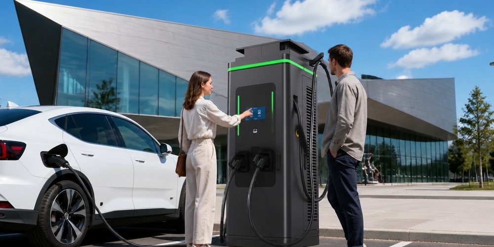
A portable DC charger is often paired with a trailer-mounted or van-integrated Battery Energy Storage System. This creates a “Mobile Power Bank” capable of delivering hundreds of kilowatts in the middle of a desert or a disaster zone.
- DC-Coupled vs. AC-Coupled Architectures: In an AC-coupled system, the battery discharges through an inverter to create AC power, which the charger then converts back to DC for the vehicle. This involves multiple conversion steps and significant energy loss. Modern portable systems prefer “DC-Coupled” architectures, where the storage battery and the charger share a common high-voltage DC bus. This increases efficiency by 5-10% and reduces the overall weight of the system by eliminating redundant transformer stages.
- Dynamic Load Balancing: When operating off-grid, the source (the storage battery) is finite. The charger’s software must dynamically adjust the charging rate based on the storage battery’s State of Charge (SoC), temperature, and the expected duration of the mission.
7.3 Solar and Renewable Integration
For long-term off-grid deployment, such as in remote research stations or military outposts, portable DC chargers are being equipped with Maximum Power Point Tracking (MPPT) inputs. This allows solar arrays to feed directly into the DC bus, trickle-charging the internal storage or providing a “boost” to the vehicle charging session. This multi-source energy management requires a sophisticated central controller that can arbitrate between solar, battery, and (if available) generator inputs to optimize for charging speed and system longevity.
Chapter 8: Strategic Deployment: Case Studies in Military Operations and Emergency Disaster Response
The portability and rapid deployment capability of DC charging technology have moved it from the realm of commercial luxury to that of strategic necessity. In high-stakes environments, the ability to move energy is as important as the ability to generate it.
8.1 Military Applications: The Silent Logistics Revolution
The modern battlefield is becoming increasingly electrified. From reconnaissance drones and robotic ground vehicles (UGVs) to hybrid-electric tactical trucks, the demand for high-power DC energy at the “tactical edge” is skyrocketing.
- Stealth and Thermal Signatures: Traditional diesel generators are loud and produce a massive thermal signature, making them easy targets for infrared sensors. A portable DC charger paired with a silent battery storage unit allows for “Silent Overwatch” and covert charging of electric assets.
- Ruggedization Beyond Commercial Standards: Military-grade portable chargers must meet MIL-STD-810H, which includes resistance to salt fog, extreme altitude, and even the electromagnetic pulse (EMP) generated by nuclear events. The enclosure is typically a Faraday cage, protecting the internal SiC electronics from external interference.
- Microgrid Integration: In a Forward Operating Base (FOB), a fleet of portable DC chargers can be networked to form a microgrid. This allows the commander to prioritize energy for life-support systems or communication arrays, diverting excess power to vehicle charging only when mission parameters allow.
8.2 Disaster Recovery and Humanitarian Aid
When a hurricane, earthquake, or wildfire knocks out the local grid, the transportation of medicine, food, and rescue personnel becomes a challenge. As rescue fleets transition to EVs, the need for “Emergency Mobile Charging” becomes critical.
- Rapid Deployment Logic: A portable DC charger can be dropped by helicopter into a disaster zone and be operational within minutes of hitting the ground. Its ability to work with a wide range of input voltages (including poor-quality power from damaged local grids or old generators) makes it an invaluable tool for NGOs and emergency services.
- Vehicle-to-Everything (V2X) as a Lifeline: In a disaster scenario, a portable DC charger can work in reverse. It can draw energy from a large EV (like a transit bus or an electric truck) and provide a high-power AC output to run a field hospital or a mobile communication center. This effectively turns every EV in the disaster zone into a mobile power station.
8.3 Fleet Recovery and Roadside Assistance
For the commercial sector, the primary use case is “Rescue Charging.” When an EV runs out of power on a busy highway, a portable DC charger is the only way to get it moving again quickly.
- The “Gallon of Electrons” Concept: Roadside assistance vehicles now carry 20kW-50kW portable units. Providing just 5-10kWh of energy (the equivalent of a gallon of gas) in under 10 minutes is enough to get the vehicle to the nearest permanent fast charger. This requires a unit that is small enough to be handled by a single operator but powerful enough to maintain high current even as the vehicle’s battery voltage rises.
- Data Logging and Billing: In a service environment, the portable charger must log every session and transmit the data via LTE/5G to the central office for billing and fleet management. This requires a secure, “always-on” connectivity module integrated into the charger’s control stack.
Chapter 9: Economic Synergy: Portable Chargers as Mobile Virtual Power Plant (VPP) Units
As the number of portable DC chargers grows, they are evolving from simple energy consumers into sophisticated grid-edge assets. When aggregated and controlled via cloud-based platforms, a fleet of portable chargers becomes a “Virtual Power Plant” (VPP), capable of providing critical services to the utility grid while generating additional revenue for the owner.
9.1 The Bi-Directional Revolution: V2G and V2H in a Mobile Context
The core of VPP integration is bi-directional power flow. While most portable chargers are designed for G2V (Grid-to-Vehicle), the next generation of high-end units is being built with “Four-Quadrant” converters. This allows energy to flow back from the vehicle’s battery into the grid (V2G) or a specific building (V2H/V2B).
- Mobile Peak Shaving: During periods of peak demand, when electricity prices are at their highest, a fleet of portable chargers connected to parked EVs can discharge energy back into the facility’s microgrid. This reduces the “Demand Charges” that industrial facilities pay to utilities, offering a significant Return on Investment (ROI).
- Frequency Regulation: The stability of the electrical grid depends on maintaining a precise frequency (50/60Hz). Portable DC chargers, with their sub-millisecond response times, are ideal for “Primary Frequency Control.” By slightly adjusting their charging or discharging rate in response to grid signals, they can help stabilize the grid more effectively than traditional thermal power plants.
9.2 The Software Stack of a Mobile VPP
Turning a piece of hardware into a VPP node requires a complex software architecture:
- Aggregator Interface: The charger must communicate with a central aggregator using protocols like OCPP 2.0.1 or IEEE 2030.5. This allows the utility to see the “Available Capacity” of the portable fleet in real-time.
- State of Health (SoH) Protection: Discharging a vehicle’s battery for grid services can lead to accelerated degradation. The VPP logic must include “Battery Guard” algorithms that ensure grid services never compromise the vehicle’s primary mission or the long-term health of its cells.
- Cybersecurity at the Edge: Since VPP nodes are connected to critical infrastructure, they are high-value targets for cyberattacks. Portable DC chargers must implement hardware-based Root of Trust (RoT), encrypted bootloaders, and secure communication channels to prevent unauthorized access to the grid control signals.
9.3 Monetizing Mobility: The “Charging-as-a-Service” (CaaS) Model
The VPP capability changes the economics of portable charging. A fleet operator can now offer “Charging-as-a-Service,” where the cost of charging is subsidized by the revenue generated from grid services. This makes portable DC infrastructure not just an operational necessity but a profitable financial asset.
Chapter 10: Future Horizons: Solid-State Storage Integration and AI-Driven Load Balancing
The trajectory of portable DC charging is pointed toward even higher power densities and more autonomous operation. We are entering the era of “Smart Portable Power.”
10.1 Solid-State Battery Integration
Current portable chargers rely on Lithium-Ion or LiFePO4 (LFP) batteries for their internal storage. The next leap will be the integration of Solid-State Batteries (SSB).
- Higher Energy Density: SSBs can offer double the energy density of traditional liquid-electrolyte batteries. This will allow for 100kW+ portable chargers that are half the size of current units.
- Enhanced Safety: Solid-state electrolytes are non-flammable, making them much safer for transport in sensitive environments like underground mines or inside cargo aircraft.
- Extreme Temperature Performance: SSBs operate more effectively in extreme cold and heat, expanding the deployment range of portable units to Arctic and Saharan environments.
10.2 AI and Machine Learning in Energy Management
As portable chargers become part of larger ecosystems, Artificial Intelligence (AI) will play a crucial role in managing the flow of energy.
- Predictive Maintenance: Machine learning algorithms will analyze the high-frequency switching data from the SiC modules to predict failures before they happen. For example, a slight change in the resonant frequency of the LLC converter could indicate a degrading capacitor, prompting a maintenance alert.
- Autonomous Load Forecasting: AI can analyze historical charging patterns and local grid conditions to decide the best time to charge the unit’s internal battery. If a major storm is predicted, the AI might prioritize keeping the storage at 100% SoC for emergency deployment, even if electricity prices are high.
- Dynamic Protocol Optimization: AI-driven communication gateways will be able to “fingerprint” new vehicle models, automatically adjusting the charging curve to maximize speed while minimizing battery stress, even for vehicles that haven’t been officially tested by the charger manufacturer.
10.3 Robotic and Autonomous Deployment
We are already seeing the first prototypes of “Autonomous Charging Robots”—essentially portable DC chargers mounted on an AGV (Automated Guided Vehicle) chassis. These units can navigate a parking garage or a factory floor, find a vehicle that needs charging, and plug themselves in using a robotic arm. This eliminates the need for human intervention and maximizes the utilization of the charging asset.
Chapter 11: Conclusion: The Strategic Role of Portable DC Power in the Net-Zero Transition
The transition to a sustainable, electrified future is a logistical challenge of unprecedented scale. While stationary infrastructure will always be the foundation, the inherent rigidity of the grid requires a flexible, mobile counterpart. The Portable DC Charger is that counterpart.
From the engineering labs where SiC semiconductors are pushed to their limits, to the disaster zones where mobile units provide a lifeline of energy, the portable charger is proving itself to be an indispensable tool. It represents the convergence of high-power electronics, advanced mechanical engineering, and sophisticated software logic.
As we look forward, the role of these units will only expand. They will become the “nervous system” of a mobile energy grid, moving power to where it is needed most, stabilizing the utility network, and ensuring that no vehicle, drone, or robotic system is ever left without the energy it needs to complete its mission. The Perfect Charging Solution is no longer a fixed point on a map; it is a mobile, intelligent, and resilient asset ready to be deployed anywhere on Earth.
Summary of Technical Specifications for a State-of-the-Art Portable DC Charger
| Parameter | Specification |
|---|---|
| Power Output | 30kW – 240kW (Modular) |
| Output Voltage Range | 200V – 1000V DC |
| Switching Frequency | 100kHz – 500kHz (SiC-based) |
| Communication Protocols | ISO 15118, DIN 70121, GB/T 27930, NACS, CHAdeMO |
| Ingress Protection | IP54 / IP65 |
| Reliability Standards | MIL-STD-810G (Vibration/Shock) |
| Cooling | Hybrid Liquid/Forced Air |
| Grid Interaction | V2G / V2H / VPP Ready |
| Weight-to-Power Ratio | < 0.8 kg/kW |
By adhering to these rigorous standards and pushing the boundaries of what is possible in power electronics, the industry is ensuring that the “Electric Revolution” is not just clean, but truly mobile.
Chapter 12: Thermal Simulation and Lifecycle Analysis: Ensuring Longevity in High-Duty Cycles
To truly understand the robustness of a portable DC charger, one must look beyond its peak performance and examine its behavior over thousands of thermal cycles. In a portable unit, the thermal stresses are afunction of ambient temperature, load cycling, connector mating frequency, and the real-world duty profile imposed by the end user. A portable charger that rides in a service van through the Mojave Desert experiences radically different thermal boundary conditions than one deployed inside a conditioned warehouse. Consequently, modern thermal design begins not with a single worst-case figure, but with a “mission profile”: a statistical distribution of ambient temperatures, charge powers, and idle periods that the unit will realistically encounter over its service life.
Finite Element Analysis and CFD-Driven Design
At the component level, Finite Element Analysis (FEA) models the conduction path from the SiC die through the direct-bonded copper substrate, the thermal interface material, and the cold plate into the coolant loop. Each layer is characterized for its thermal resistance and coefficient of thermal expansion (CTE), because mismatched CTE between a silicon carbide module and an aluminum heat sink is a primary driver of solder fatigue and delamination after repeated thermal cycling.
Computational Fluid Dynamics (CFD) complements FEA by modeling the air and liquid flow paths. Engineers simulate airflow through the forced-air sections at high ambient temperatures, verify that the liquid cooling loop keeps the coolant within its recommended range, and hunt for “hot spots” where stagnant air pockets could compromise component life. The result is a cooling architecture in which every watt of loss has a defined path to the environment.
Thermal Cycling and Component Derating
Thermal cycling is the silent killer of power electronics. Every time the charger ramps from standby to full power, the semiconductor junction temperature swings by tens of degrees Celsius. Over a decade of operation, that represents tens of thousands of cycles. The industry-standard response is derating: components are specified not at their datasheet maximums but at 70-80% of rated stress, extending predicted lifetime by an order of magnitude.
Capacitors deserve special attention. Electrolytic capacitors, with their liquid electrolyte, age roughly twice as fast for every 10°C increase in operating temperature. Leading designs therefore use film capacitors in the DC link and reserve electrolytics only where unavoidable — while monitoring internal temperatures through charger telemetry and reporting component health via the OCPP data model, so the operator sees degradation coming long before it becomes a failure.
Accelerated Life Testing and Validation
Simulation is only as good as its validation. High-end manufacturers subject portable units to accelerated life testing: temperature cycling from -40°C to +85°C, sinusoidal and random vibration per MIL-STD-810G, and salt-spray testing for coastal deployments. Combined with HALT (Highly Accelerated Life Testing) to surface latent failure modes, this regime lets engineers predict mean time between failures (MTBF) with statistical confidence before the first unit ships.
The Lifecycle Payoff
The economic argument is straightforward. A portable DC charger that delivers 5,000-10,000 charging cycles with minimal degradation returns its capital cost many times over through equipment rental, emergency-response contracts, and fleet support fees. Thermal engineering is the discipline that guarantees those cycles — transforming a promising prototype into a durable, bankable asset that can be deployed anywhere on Earth with confidence.
Key Takeaways
- Thermal design starts with a realistic mission profile, not a datasheet worst case.
- FEA and CFD simulation, validated by accelerated life testing, are essential to predicting lifetime in high-duty portable applications.
- Component derating and careful selection of capacitors and power modules determine whether a portable charger lasts five years or fifteen.
- Hybrid liquid/forced-air cooling delivers the <0.8 kg/kW power density that makes portable high-power charging practical.
Contact MIDA Power
MIDA Power’s portable DC charger platforms are engineered with exactly this level of thermal rigor — from SiC power stages to hybrid liquid cooling, validated against MIL-STD-810G. For complete technical specifications, thermal simulation reports, or a tailored quotation for your deployment, contact our engineering sales team today. Our specialists will help you size the right portable or trailer-mounted solution for your grid, fleet, or disaster-recovery requirements.
Post time: Aug-09-2026
