
 Portable EV Charger
 Home EV Wallbox
 DC Charger Station
 BESS Charging Station
 V2G V2H V2V V2L
 EV Charging Module
 DC Charging Connector
 EV Accessories
Japan Liquid-Cooled Ultra-Fast Charging 2026: 400kW+ Technology, Liquid-Cooled Cables and 1500V Architecture
Key Takeaways
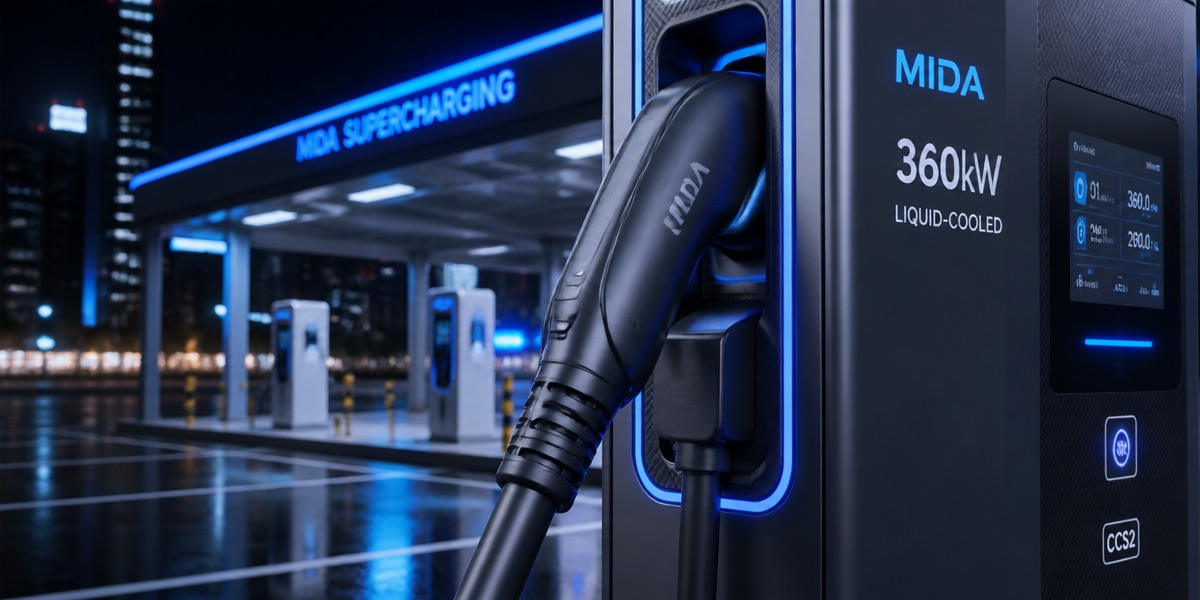
- Liquid cooling principle: coolant circulates inside the cable to remove heat, enabling thinner cables, gun heads over 40% lighter than air-cooled units, and 600A continuous current.
- 400kW+ architecture: split-type power cabinet plus liquid-cooled terminals with dynamic multi-gun power sharing; single-gun peaks reach 400kW.
- 1500V reserve: with CHAdeMO 3.0 (ChaoJi) and CCS2 high-voltage trends, a 1500V bus architecture becomes the standard for ultra-fast stations.
- Charging experience: 10 minutes adds 300km+, making highway long-distance charging feel like refueling and sharply shortening dwell time.
- Deployment essentials: connection capacity, upgrade lead time, BESS buffering and certification scheduling decide how fast an ultra-fast station opens.
Japan Liquid-Cooled Ultra-Fast Charging: Why It Is the 2026 Main Line
Japan’s rapid charging network today is “enough quantity, too little power”: of roughly 14,000–16,000 active rapid charging ports, 50kW-class units dominate and average single-port power is only about 27–40kW—badly mismatched with the ultra-fast requirements implied by the 2030 target of 300,000 ports, and liquid-cooled ultra-fast charging (400kW+) is the equipment answer that closes the gap. Liquid cooling solves two bottlenecks: air-cooled cables become too heavy and too hot above 250A to support high power, while liquid-cooled cables carry heat away so 600A continuous current and lightweight operation become reality. Combined with 800V vehicle volume and CHAdeMO 3.0 (ChaoJi) industrialization, 2026 becomes the year Japan liquid-cooled ultra-fast charging shifts from pilot to large-scale deployment. This article covers technology principles, architecture design, comparison analysis, deployment essentials and a scene case.
H2: Liquid-Cooled Cable Technology: How 600A Current Is Achieved
The cooling revolution in liquid-cooled ultra-fast charging happens at three levels: liquid-cooled power modules (cold plates attached directly to SiC modules, with coolant removing junction heat), liquid-cooled cables (coolant pipes arranged around the cable conductors, with a micro circulation pump in the gun head cycling coolant back to the host heat exchanger), and whole-machine thermal management (host-side heat exchangers with closed-loop air or water cooling). Data worth citing: liquid-cooled cables raise charging current from the air-cooled limit of about 250A to 600A, and since charging power equals current times voltage, a single gun on an 800V platform can deliver 480kW; the liquid-cooled gun head weighs only about 50–60% of an air-cooled unit (roughly 1.5–2.5kg) with better cable flexibility—for Japanese scenarios with high shares of elderly and female users, the lightweight gun head directly determines charging experience and operational safety.
H3: Liquid-Cooled Cable vs Air-Cooled Cable Comparison Table
| Comparison dimension | Air-cooled cable | Liquid-cooled cable |
|---|---|---|
| Continuous current limit | Approx. 250A | 600A (higher possible) |
| Gun head weight | Approx. 3–4kg | Approx. 1.5–2.5kg |
| Cable diameter | Thick (large copper cross-section) | Thin (coolant assists heat removal) |
| Single-gun power support | Approx. 150–180kW | 400kW+ |
| Cooling method | Natural air cooling | Coolant circulation + host heat exchange |
| Maintenance focus | Low | Monitor coolant level / flow |
| Suitable scenarios | 60–180kW stations | 350kW+ ultra-fast stations |
H2: 400kW+ Ultra-Fast Architecture: Split-Type Power Cabinet and Liquid-Cooled Terminals
Japan 400kW+ ultra-fast stations adopt a split architecture: the power cabinet (centralized power units, air- or liquid-cooled) is separated from the liquid-cooled terminals (2–8 gun positions) and connected by liquid-cooled cables, with EMS/power distributors dynamically allocating power on demand. The split design’s advantages are especially pronounced in Japan: the power cabinet can be placed in an electrical room or container (avoiding weather and footprint), terminals are lightweight and placed beside parking slots, expansion only adds power modules while reusing terminals, and multi-gun power sharing maximizes station throughput (a 4-gun 400kW cabinet delivers 240kW single-gun peaks or 100kW per vehicle when four charge simultaneously).
H3: 400kW Liquid-Cooled Ultra-Fast Station Key Deployment Parameter Table
| Deployment parameter | Recommended value / note |
|---|---|
| Station power | 400kW–480kW (power cabinet) |
| Terminal configuration | 4–8 liquid-cooled guns (CHAdeMO + CCS2 mixed) |
| Bus voltage | 1000V / 1500V (ChaoJi reserve) |
| Power connection | 6.6kV high-voltage connection or low-voltage contract + BESS buffer |
| Single-gun peak | 200–400kW (800V vehicles) |
| Charging speed | 10 minutes adds 300km+ (800V vehicles) |
| Certification requirements | PSE + CHAdeMO conformance + type certification |
H2: 1500V Architecture and CHAdeMO 3.0: The Standard Main Line for Japan Ultra-Fast Charging
The main line of Japan ultra-fast charging standards is CHAdeMO 3.0 (the ChaoJi specification jointly advanced by Japan and China): 1500V bus, up to 600kW, compatible with both CHAdeMO and GB/T ecosystems, and positioned as the industry standard for Japan’s next-generation ultra-fast charging. In 2026, ChaoJi enters the pilot-validation phase, with industrialization expected in 2027–2028. For ultra-fast stations deployed in 2026, the recommended strategy is “1000V delivery with 1500V reserve”: power modules rated above 1200V, bus design reserved for 1500V upgrades, and liquid-cooled cables designed for 600A—avoiding retrofits when ChaoJi vehicles arrive in 2027. Meanwhile, imported 800V vehicles (CCS2) are growing, so station gun positions should be configured as a CHAdeMO/CCS2 mix.
H2: Deployment Essentials: Power Connection, Certification and BESS Coordination for 400kW+ Stations
The engineering constraints of a 400kW+ ultra-fast station concentrate in three areas. Power connection: a 400kW station typically needs a 6.6kV high-voltage connection with a 6–12 month upgrade lead time; constrained properties can use a “low-voltage contract plus BESS buffer” plan (the BESS keeps grid-side peaks inside the contract, shortening the lead time to 2–5 months). Certification: the power cabinet and liquid-cooled terminals are type-tested for PSE and CHAdeMO conformance, with single-type cycles above 6 months—modular design so one type covers multiple power configurations is recommended. Construction: liquid-cooling installation involves coolant filling, pipeline leak testing and flow calibration by certified service providers, and liquid-cooled cable storage plus low-temperature anti-freeze (Hokkaido winter) must be designed in.
H3: 400kW Ultra-Fast Station Power Connection Options Comparison Table
| Connection option | Suitable scenarios | Upgrade lead time | Initial cost | Note |
|---|---|---|---|---|
| 6.6kV high-voltage | Large SA/PA, new properties | 6–12 months | High | Highest ceiling; final form for ultra-fast scale-up |
| Low-voltage upgrade | Existing properties with contract headroom | 2–6 months | Medium | Power ceiling limited by contract |
| Low-voltage + BESS buffer | Constrained connection, fast deployment | 2–5 months | Medium-high | Grid-side peaks cut 30–50% |
| Mobile storage-charging unit | Temporary sites, pilot validation | 1–2 months | Medium | Operate first, then fix |
H2: Scene Narrative: A Highway SA 400kW Liquid-Cooled Ultra-Fast Station Rollout
In June 2026, a SA on the Tohoku Expressway planned a 4-gun 400kW liquid-cooled ultra-fast station to serve holiday traffic. The team first ran engineering pre-checks: the SA’s existing connection contract was 350kW, exceeding the 400kW cabinet’s peak—a full upgrade would take 12 months and miss the winter peak, so the team chose “contract upgrade to 450kW plus 120kW/141kWh BESS buffer,” compressing the lead time to 4 months. On equipment, the station used a power cabinet with 4 liquid-cooled terminals (2 CHAdeMO 2.0, 2 CCS2, with ChaoJi upgrade positions reserved) on a 1500V-designed bus. On certification, PSE and CHAdeMO conformance tests ran in parallel, with certificates obtained in August. The station launched in October: real-world tests showed 360kW single-gun peaks on 800V vehicles, about 280km of range added in 10 minutes, and the BESS shaving 35% of peaks during high-traffic hours while keeping basic charges within budget. Winter testing showed no power derating for the liquid-cooled cables at -10°C, with anti-freeze coolant design working normally. The station manager’s verdict: liquid-cooled ultra-fast charging turns highway charging from “queuing for half an hour” into a “refueling-like experience”—400kW+ is not a spec race but a fundamental rebuild of the long-distance travel experience.
H2: 7 High-Frequency FAQs
- Q: What is the difference between liquid-cooled ultra-fast charging and normal fast charging? A: Liquid-cooled ultra-fast charging uses liquid-cooled cables and liquid-cooled power modules to support 600A current and 400kW+ single-gun power, adding 300km in 10 minutes; normal fast charging (air-cooled) delivers 150–180kW per gun.
- Q: What power connection conditions does a 400kW ultra-fast charger need? A: Typically a 6.6kV high-voltage connection or low-voltage contract upgrade; with a constrained connection, use “contract plus BESS buffer” to keep grid-side peaks inside the contract.
- Q: Can liquid-cooled cables leak? A: Production liquid-cooled cables use double-layer tube and sealing designs, with host-side level and pressure monitoring and automatic shutdown alarms on leaks; maintenance focuses on periodic level and seal checks.
- Q: When will CHAdeMO 3.0 (ChaoJi) be usable? A: It enters pilot validation in 2026, with industrialization expected in 2027–2028; stations deployed in 2026 should reserve the 1500V architecture to avoid retrofits.
- Q: How much lighter is a liquid-cooled gun head than an air-cooled one? A: Liquid-cooled gun heads weigh about 1.5–2.5kg, over 40% lighter than air-cooled units, with more flexible cables—easier operation for elderly and female users.
- Q: Which Japanese scenarios suit liquid-cooled ultra-fast stations? A: Highway SA/PA, urban ultra-fast flagship stations, logistics fleet bases and commercial facility parking; high-power, short-dwell scenarios yield the highest returns.
- Q: Are operation and maintenance costs higher for liquid-cooled ultra-fast charging? A: Coolant management, level monitoring and pipeline checks add tasks, but lower component failure rates and simpler heat dissipation keep the total increase modest—leading operators estimate about 10–20%.
H2: Related Products and Internal Links
Product support for Japan 400kW+ liquid-cooled ultra-fast charging: flagship stations can deploy floor-standing DC charger stations (320kW–480kW liquid-cooled, 600A liquid-cooled cables, multi-gun dynamic power sharing, 1500V architecture reserve), the main form for highway SA/PA ultra-fast rollout; all power segments are covered by DC fast charging stations (20kW–480kW) matched to station tiers; connection-constrained sites use BESS charger stations (120kW/141kWh mobile) for power buffering and disaster backup, paired with energy storage systems for valley-charge/peak-discharge that turns connection constraints into cost advantages. The recommended path is to work with MIDA on “connection pre-screening → power architecture → standard reserve → certification scheduling” to convert Japan liquid-cooled ultra-fast charging from a technical concept into an operating asset for the 400kW+ era.
Post time: Aug-17-2026
