
 Portable EV Charger
 Home EV Wallbox
 DC Charger Station
 BESS Charging Station
 V2G V2H V2V V2L
 EV Charging Module
 DC Charging Connector
 EV Accessories
The Definitive Technical Guide to Ultra-Fast EV Charging: Exploring 800V+ High-Voltage Architectures, Modular SiC/GaN Power Electronics, Liquid-Cooled Infrastructure, Charging Curve Optimization, and the Engineering of Megawatt-Scale Sustainable Mobility Solutions
Chapter 1: The Evolution of EV Charging and the Shift to Ultra-Fast Infrastructures
The global transition toward electric mobility has reached a critical inflection point. While early adopters were content with overnight AC charging and first-generation DC fast chargers (50 kW), the mass-market transition requires a charging experience that rivals the convenience of internal combustion engine (ICE) refueling. This demand has birthed the era of Ultra-Fast Charging (UFC), typically defined as DC charging at power levels of 150 kW to 350 kW and beyond.
Ultra-fast charging is not merely a quantitative increase in power; it is a qualitative shift in engineering requirements. To deliver 350 kW to a vehicle, the system must manage currents exceeding 500A at 400V, or higher voltages to keep current—and thus resistive heating—manageable. The evolution from the CHAdeMO and early CCS standards to the latest high-power liquid-cooled systems represents a decade of intense innovation in power electronics, materials science, and thermal management.
The necessity for UFC is driven by two primary factors: range anxiety and the emergence of long-range EVs with large battery packs (80 kWh to 150 kWh+). A 50 kW charger takes over an hour to provide an 80% charge to a modern luxury EV. An ultra-fast charger can accomplish the same in 15 to 20 minutes. This chapter explores the historical context, the regulatory landscape (such as AFIR in Europe), and the technical barriers that were overcome to make sub-20-minute charging a reality for the general public.
Chapter 2: High-Voltage Architecture: The Transition from 400V to 800V+ and Its Implications for System Efficiency
The most significant architectural shift in the EV industry recently has been the transition from 400V battery systems to 800V (and even 900V or 1000V) architectures. This shift is fundamentally driven by Ohm’s Law and the physics of heat dissipation.
In a 400V system, delivering 350 kW requires a current of nearly 875 Amperes. According to the formula P = I²R, the heat generated in the cables, connectors, and internal battery busbars increases with the square of the current. To handle 875A, cables would need to be prohibitively thick and heavy, making them difficult for consumers to handle. By doubling the voltage to 800V, the required current for the same 350 kW output is halved to approximately 437A.
The benefits of 800V+ architectures extend beyond the charging cable:
- Reduced Weight and Volume: Thinner internal wiring and smaller motor windings reduce the overall vehicle weight.
- Increased Efficiency: Lower resistive losses mean more energy reaches the battery and less is wasted as heat during both charging and driving.
- Faster Charging Speeds: 800V systems can maintain peak charging rates for longer durations because they generate less heat within the battery’s internal resistance.
However, the 800V transition introduces challenges in component insulation, semiconductor breakdown voltages, and compatibility with existing 400V infrastructure. Many 800V vehicles, such as the Porsche Taycan or the Hyundai Ioniq 5, utilize onboard DC/DC converters or motor-inverter configurations to “boost” 400V charger output to battery-compatible levels, ensuring backward compatibility while pushing the frontier of high-speed charging.
Chapter 3: Modular Power Electronics: The Heart of Ultra-Fast Charging Units
Modern ultra-fast chargers are no longer monolithic blocks of power electronics. Instead, they are built using a modular philosophy. A 350 kW charger typically consists of multiple 20 kW or 30 kW power modules stacked in parallel within a power cabinet.
Benefits of Modularity:
- Scalability: Charge point operators (CPOs) can start with a 150 kW installation and add modules to reach 300 kW as demand grows.
- Redundancy and Reliability: If one module fails, the charger can continue to operate at a reduced power level rather than going completely offline. This is crucial for maintaining high “uptime” metrics in public charging networks.
- Ease of Maintenance: Technicians can swap out a faulty module in minutes without needing specialized heavy-lifting equipment.
- Dynamic Power Allocation: Modular systems allow for “power sharing” between multiple charging dispensers. If a station has a 350 kW power bank and two cars are charging, the system can intelligently allocate 175 kW to each, or 250 kW to one and 100 kW to the other based on the vehicles’ state of charge (SoC).
The internal architecture of these modules involves complex multi-stage conversion. Typically, an AC/DC stage with Power Factor Correction (PFC) is followed by a galvanically isolated DC/DC stage. The use of resonant topologies, such as LLC converters, allows these modules to achieve efficiencies exceeding 97%, which is vital when managing the thermal load of a multi-megawatt charging hub.
Chapter 4: Semiconductor Revolution: In-depth Analysis of SiC and GaN in Ultra-Fast Charging Converters
The push for higher power density and efficiency in ultra-fast chargers has led to the replacement of traditional Silicon (Si) IGBTs with Wide Bandgap (WBG) semiconductors: Silicon Carbide (SiC) and Gallium Nitride (GaN). These materials are the linchpins of the modern power electronics revolution, offering physical properties that far exceed the limits of traditional silicon.
Silicon Carbide (SiC): The High-Power Workhorse SiC MOSFETs are particularly suited for the high-voltage (800V-1200V) requirements of UFC stations. Unlike standard silicon, SiC has a wider energy bandgap (3.26 eV compared to 1.12 eV for Si), which allows it to operate at higher temperatures and withstand higher breakdown voltages.
- Switching Frequency and Magnetics: SiC can switch at much higher frequencies than Si IGBTs—often in the range of 50 kHz to 150 kHz for high-power stages. This allows engineers to reduce the size and weight of passive components like inductors and transformers. At these frequencies, the physical volume of the magnetic cores can be reduced by up to 40%, which is critical for fitting a 350 kW unit into a standard-sized cabinet.
- Thermal Conductivity and Cooling: SiC’s thermal conductivity is nearly 3.5 times higher than that of Silicon. This enables more efficient heat transfer from the junction to the heatsink. In practical terms, this means that a SiC-based charger can operate at full power in ambient temperatures where a Silicon-based charger would be forced to derate its output to avoid overheating.
- Total Cost of Ownership (TCO): While SiC chips are more expensive than Si chips, the system-level savings are substantial. Reduced cooling requirements, smaller enclosures, and 2-3% higher efficiency translate to significant savings over the 10-15 year lifespan of a charging station. For a CPO, every watt saved is a watt that doesn’t have to be paid for, directly impacting the bottom line.
Gallium Nitride (GaN): Precision and Efficiency at Scale While SiC dominates the very high-power DC/DC stages, GaN is making inroads in the AC/DC PFC stages and auxiliary power supplies. GaN offers even higher electron mobility than SiC, enabling ultra-fast switching speeds (up to several MHz).
- Zero Reverse Recovery: GaN HEMTs (High Electron Mobility Transistors) have zero reverse recovery charge (Qrr). This characteristic eliminates a major source of switching loss and EMI in hard-switching topologies, allowing for even higher efficiency in the front-end AC/DC conversion stage.
- Integration and Packaging: GaN-on-Si technology allows for the integration of the power switch, gate driver, and protection circuitry into a single package. This “Power IC” approach reduces parasitic inductance and simplifies the design of the modular power blocks used in ultra-fast chargers.
- The Hybrid Approach: The most advanced chargers now use a hybrid approach: GaN for the high-speed, high-efficiency front-end and SiC for the rugged, high-voltage DC/DC output stage. This combination leverages the strengths of both WBG materials to achieve system efficiencies previously thought impossible.
The integration of SiC and GaN into modular chargers requires sophisticated gate drivers capable of managing the high dV/dt (up to 100 V/ns) and di/dt levels. Furthermore, PCB layouts must be meticulously designed to minimize stray inductance, which can cause voltage overshoots that exceed the semiconductor’s breakdown voltage. The transition to WBG is not just a component swap; it is a total paradigm shift in power electronics engineering.
Chapter 5: Thermal Management: Design and Engineering of Liquid-Cooled Cables and Connectors
Delivering 350 kW to 500 kW through a handheld cable presents a massive thermal challenge. Without active cooling, a cable capable of carrying 500A would be as thick as a human arm and nearly impossible to bend. The solution is active liquid cooling, a technology borrowed from high-performance computing and industrial machinery.
Liquid-Cooled Cables: The Physics of Heat Removal A liquid-cooled cable features internal channels through which a coolant (typically a mixture of water and glycol or a dielectric synthetic oil like Midel) circulates. This coolant absorbs the heat generated by the copper conductors—which can reach temperatures over 100°C without cooling—and carries it back to a heat exchanger within the charging station.
- Cable Geometry and Fluid Dynamics: Modern cables use a multi-core design where the coolant flows in direct contact with the conductor insulation or even the conductors themselves. Engineers must balance the fluid flow rate with the pressure drop to ensure efficient cooling without requiring a massive pump. The goal is to keep the surface temperature of the cable below 50°C for user safety, even during a 500A session.
- Weight Reduction: By using liquid cooling, the cross-sectional area of the copper conductors can be reduced by 60-70%. This makes the cable significantly lighter and more flexible. A 350 kW liquid-cooled cable can be as thin as a standard 50 kW uncooled cable, ensuring that any driver, regardless of physical strength, can easily plug in their vehicle.
- Reliability and Durability: These cables are subjected to extreme conditions: they are dropped, driven over, and exposed to UV radiation and freezing temperatures. The internal cooling tubes must be flexible enough to withstand thousands of bending cycles without leaking. High-performance polymers like TPU (Thermoplastic Polyurethane) are often used for the outer jacket to provide the necessary durability.
Connector Design (CCS2 and MCS): The Thermal Bottleneck The connector interface is the most thermally stressed point in the entire charging system. High contact resistance at the pins—often caused by wear, dirt, or oxidation—can lead to localized hotspots that can melt the connector or the vehicle’s inlet.
- Active Pin Cooling and Heat Pipes: To combat this, high-end ultra-fast chargers now incorporate cooling channels that extend all the way into the connector head. Some designs even use heat pipes or liquid-filled “slugs” to draw heat away from the pins and into the main cooling loop.
- Contact Material Science: The pins are typically made of high-conductivity copper alloys and plated with silver or gold. Advanced contact designs, such as multi-lamella or spring-loaded contacts, ensure a large contact area and low resistance even after thousands of mating cycles.
- Integrated Thermal Sensors: Every ultra-fast connector is equipped with multiple NTC (Negative Temperature Coefficient) thermistors located as close to the contact pins as possible. The charger’s controller monitors these sensors in real-time. If the temperature at the pins starts to rise unexpectedly, the system will immediately throttle the current to a safe level, protecting both the charger and the vehicle.
The engineering of liquid-cooled infrastructure is a testament to the interdisciplinary nature of ultra-fast charging, requiring expertise in electrical engineering, fluid mechanics, materials science, and human factors.
Chapter 6: Charging Curve Optimization: Balancing Speed, Efficiency, and Thermal Limits
An ultra-fast charger does not deliver its peak power for the entire duration of the charging session. Instead, it follows a dynamic “charging curve” that is carefully orchestrated by the vehicle’s Battery Management System (BMS). Optimizing this curve is a delicate dance between raw speed, energy efficiency, and the long-term integrity of the battery cells.
The Anatomy of a Charging Curve: A typical ultra-fast charging session is divided into several distinct phases, each with its own physical and chemical constraints:
- Preparation and Handshake: Before the current flows, the charger and vehicle perform a digital handshake (via ISO 15118 or DIN 70121). The BMS assesses the battery’s state of charge (SoC), internal temperature, and health (SoH) to determine the maximum safe charging rate.
- Ramp-Up Phase: The current is increased rapidly but controlled to avoid voltage spikes.
- Bulk Charge (Constant Current – CC): In the early-to-mid stages (typically 0% to 50% SoC), the battery’s internal resistance is at its lowest, allowing it to accept peak currents. This is the “headline” power level (e.g., 350 kW) that manufacturers advertise. However, this phase is also when the most heat is generated within the cells due to Joule heating (I²R).
- Thermal Throttling and Plateau: As the internal temperature of the cells approaches the safety limit (often around 45°C to 55°C), the BMS will signal the charger to reduce the power. A sophisticated BMS doesn’t just cut the power; it modulates it in a “plateau” fashion to maximize energy intake while keeping the cooling system within its operational capacity.
- Tapering (Constant Voltage – CV): As the battery approaches 80% SoC, the voltage of the individual cells reaches the maximum allowable limit (e.g., 4.2V or 4.4V depending on chemistry). To avoid overvoltage, the charger must switch to a constant voltage mode, where the current naturally tapers off. This is why the final 20% of the charge is significantly slower, often taking as long as the entire 10-80% portion.
Intelligent Optimization and Real-Time Feedback: Modern EVs use advanced strategies to “stretch” the charging curve:
- Active Battery Pre-conditioning: If a driver selects an ultra-fast charger as a destination in the navigation system, the car’s thermal management system will proactively heat or cool the battery. If the battery is too cold (e.g., in winter), the ions move too slowly, causing lithium plating. If it’s too hot, the peak rate is unattainable. Pre-conditioning ensures the battery hits the “goldilocks zone” (approx. 25°C-35°C) the moment the plug is inserted.
- Cell-Level Monitoring: Advanced BMS architectures now monitor the temperature and voltage of every single cell or small parallel group, rather than just the average pack temperature. This allows the system to push the battery closer to its theoretical limits by identifying and managing the “weakest link” in the pack.
- Predictive Modeling and Machine Learning: Some manufacturers use “digital twin” models of the battery pack to predict thermal behavior minutes in advance. By anticipating heat buildup, the BMS can start increasing cooling pump speeds before the heat peaks, allowing for a longer duration of high-power charging.
The “V-Curve” and “Square Curve” Trends: While early fast chargers followed a simple triangular taper, the latest 800V vehicles aim for a “square” curve, where high power is maintained for as long as possible before a sharp drop at high SoC. Achieving this requires not only better cell chemistry but also significantly more powerful on-board cooling systems capable of dissipating 10-20 kW of waste heat during the charging process.
Chapter 7: Battery Health and Lifespan: Assessing the Impact of Ultra-Fast Charging on Li-ion Degradation
One of the most persistent concerns among EV owners and fleet managers is the impact of ultra-fast charging on long-term battery health. While the convenience of UFC is undeniable, the extreme physical and chemical stresses involved can, if not managed correctly, lead to premature capacity loss and increased internal resistance.
The Microscopic View of Degradation: To understand the impact of UFC, we must look at what happens inside the battery at the atomic level during a 500A charge:
- Lithium Plating and Dendrite Formation: This is the most critical risk. During high-rate charging, if the rate of lithium-ion arrival at the anode exceeds the rate at which they can be intercalated (inserted) into the graphite lattice, the ions begin to deposit as metallic lithium on the surface. This “plating” is often irreversible and reduces the amount of active lithium. Furthermore, these deposits can grow into needle-like structures called dendrites, which can eventually pierce the separator and cause a catastrophic internal short circuit.
- Solid Electrolyte Interphase (SEI) Instability: The SEI is a protective layer that forms on the anode during the first few cycles. High temperatures and high currents can cause the SEI to crack and reform, consuming active lithium and electrolyte in the process. This leads to a gradual increase in the battery’s internal resistance, which manifests as reduced performance and even slower charging speeds over time.
- Particle Cracking and Lattice Stress: The rapid influx of lithium ions causes the electrode particles to swell. At ultra-fast rates, the resulting mechanical stress can be so intense that the particles physically crack. This isolates portions of the electrode material from the electrical circuit, leading to a permanent loss of capacity.
Mitigation and The Role of Modern Engineering: Despite these risks, modern EV batteries are proving to be remarkably resilient to fast charging, thanks to several key engineering breakthroughs:
- Tabless Cell Designs: Innovations like Tesla’s 4680 tabless cells significantly reduce the internal resistance of the cell by providing a much larger path for electron flow. Lower resistance means less heat is generated during ultra-fast charging, which directly mitigates thermal degradation.
- Advanced Electrolyte Additives: Chemists have developed proprietary electrolyte mixtures that stabilize the SEI layer and facilitate faster ion transport, reducing the likelihood of lithium plating even at high C-rates.
- Dynamic Derating and Health Monitoring: The BMS doesn’t just monitor the battery; it tracks its “State of Health” (SoH) over time. If the system detects early signs of degradation, it will permanently adjust the charging curve to a more conservative profile to protect the remaining lifespan of the pack.
- Silicon-Carbon Anodes: The transition from pure graphite to silicon-carbon composite anodes allows for faster lithium-ion absorption and higher energy density. Silicon can store more lithium than graphite, but it also expands more; modern binder technologies are solving the expansion issue, enabling cells that can handle 4C or even 6C charging rates without significant damage.
Real-World Data vs. Laboratory Fears: Large-scale data analysis from hundreds of thousands of EVs in the field suggests that for vehicles with active thermal management (liquid cooling), the difference in degradation between those that frequently fast-charge and those that mostly slow-charge is less than 2-3% over a 100,000-mile period. This indicates that the engineering safeguards—BMS logic, cooling systems, and cell chemistry—are doing their job effectively. However, the industry continues to push for even more robust solutions to ensure that ultra-fast charging can be used daily without any compromise to the 10-15 year lifespan expected of modern vehicles.
Chapter 8: Communication and Smart Connectivity: Protocols, Security, and Vehicle-to-Grid (V2G) Integration
An ultra-fast charger is more than a power delivery device; it is a sophisticated node in a digital network. The communication between the vehicle, the charger, and the grid is the “intelligence” that makes the system work.
ISO 15118 and Plug & Charge: The ISO 15118 standard is the bedrock of modern EV connectivity. It enables “Plug & Charge,” a feature where the vehicle and charger automatically handle authentication, authorization, and billing via encrypted digital certificates. This eliminates the need for RFID cards or mobile apps, providing a seamless user experience.
- Security: ISO 15118 uses Public Key Infrastructure (PKI) to ensure that the communication between the car and the charger is secure from man-in-the-middle attacks.
- Data Exchange: The protocol allows the vehicle to share detailed battery data, such as capacity, SoC, and thermal health, enabling the charger to optimize its power delivery.
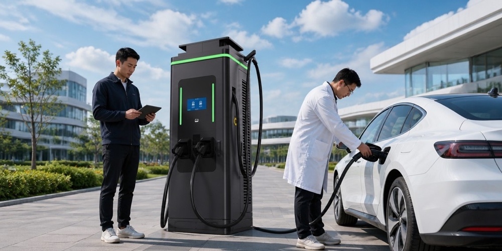
Smart Charging and Load Management: As charging stations scale to multiple megawatts, they must communicate with the utility grid to manage load.
- OCPP (Open Charge Point Protocol): This protocol allows the charging station to communicate with a central management system (CSMS). The CSMS can send commands to throttle charging speeds during times of peak grid demand or high energy prices.
- V2G and V2X: Ultra-fast chargers are increasingly being designed for bi-directional power flow. In a Vehicle-to-Grid (V2G) scenario, the EV acts as a mobile energy storage unit, feeding power back into the grid to stabilize frequency or provide emergency backup during outages. While currently more common in AC systems, DC V2G is the future of grid-integrated mobility.
Chapter 9: Grid Integration and Energy Storage: Managing Megawatt-Level Peaks with Microgrids and Second-Life Batteries
The deployment of ultra-fast charging hubs poses a significant challenge to the electrical grid. A station with ten 350 kW chargers requires a peak supply of 3.5 MW—roughly equivalent to the power needs of a small town. Upgrading the local grid infrastructure to support this can be prohibitively expensive and time-consuming.
The Role of On-Site Energy Storage Systems (ESS): To avoid massive grid upgrade costs, many CPOs are integrating stationary batteries at charging sites.
- Peak Shaving: The stationary battery charges slowly from the grid during periods of low demand and discharges rapidly to assist the chargers when an EV arrives. This reduces the peak load on the utility transformer.
- Second-Life Batteries: EV batteries that have degraded below 70-80% capacity (and are no longer suitable for vehicles) are being repurposed for stationary storage at charging hubs. This provides a sustainable “circular economy” solution for battery waste.
Microgrid Integration and Renewables: Ultra-fast charging hubs are becoming mini-microgrids.
- Solar Canopies: Large solar arrays installed over the charging stalls provide renewable energy directly to the site, reducing the carbon footprint of the charging process.
- Local Controllers: Intelligent controllers manage the flow of energy between the grid, the solar panels, the stationary battery, and the EV chargers in real-time, optimizing for both cost and carbon intensity.
- DC-Coupled Systems: By using a common DC bus for the solar panels, storage battery, and EV chargers, manufacturers can eliminate multiple AC/DC conversion stages, improving overall system efficiency by 5-10%.
Chapter 10: The Future Horizon: Megawatt Charging Systems (MCS) for Heavy-Duty Transport and Beyond
While 350 kW is sufficient for passenger cars, it is woefully inadequate for the electrification of the heavy-duty transport sector. A Class 8 electric truck, such as the Tesla Semi or the Volvo VNR Electric, may have a battery capacity exceeding 800 kWh. Charging such a beast at 350 kW would take over two hours—far too long for a commercial fleet operator. Enter the Megawatt Charging System (MCS).
Engineering the Megawatt Frontier: The MCS standard is designed to support charging at up to 3.75 Megawatts (3,000 Amperes at 1,250 Volts). Achieving this requires a monumental leap in engineering:
- The Connector Revolution: The MCS connector is fundamentally different from the CCS standard. It is designed for robotic or heavy-duty manual handling and features significantly larger contact areas. The pins are not just silver-plated; they are designed with advanced liquid cooling jackets that can dissipate kilowatts of heat from the connection interface alone.
- Ultra-High Voltage (1250V+): Moving to 1250V reduces the current required to hit the megawatt mark, but it introduces extreme challenges in dielectric insulation and safety. Air gaps must be larger, and solid insulation must be of the highest quality to prevent tracking and arcing.
- Safety Interlocks: At megawatt levels, any fault can be catastrophic. MCS includes hardware-level “safe state” mechanisms that can interrupt thousands of amps in milliseconds.
Use Cases Beyond Long-Haul Trucking: The implications of MCS extend far beyond the highway.
- Electric Aviation: Small regional electric aircraft will require megawatt-level turnaround times to be economically viable.
- Maritime Electrification: Electric ferries and tugboats, which operate on short, intense duty cycles, are perfect candidates for megawatt charging during brief port stays.
- Mining and Construction: The heavy machinery used in these industries is moving toward electrification, and MCS will be the standard that keeps these giants moving without long downtimes.
Chapter 11: Global Infrastructure Standards and the Geopolitics of Ultra-Fast Charging
The race to dominate the ultra-fast charging market is not just a technical competition; it is a geopolitical one. The standards adopted today will dictate the flow of energy and capital for decades.
The War of Standards: CCS vs. NACS vs. GB/T vs. CHAdeMO
- CCS (Combined Charging System): The dominant standard in Europe and formerly in North America. Its strength lies in its support for both AC and DC charging in a single port and its sophisticated ISO 15118 communication backbone.
- NACS (North American Charging Standard): Developed by Tesla, NACS has recently become the de facto standard in North America, with major manufacturers like Ford, GM, and Rivian switching to it. Its primary advantage is its compact, lightweight connector and the sheer reliability of the Tesla Supercharger network.
- GB/T and ChaoJi: China, the world’s largest EV market, uses the GB/T standard. However, the new “ChaoJi” standard, a collaboration between China and Japan, aims to create a unified ultra-fast charging standard capable of 900 kW+, potentially bridging the gap between eastern and western systems.
- CHAdeMO: Once the pioneer of fast charging, CHAdeMO is losing ground globally but remains relevant in Japan and for V2G applications due to its early adoption of bi-directional capabilities.
Geopolitical Implications: Control over charging standards and the underlying semiconductor supply chains (specifically SiC and GaN) is a matter of national security. Governments are subsidizing the domestic production of WBG semiconductors to ensure they are not reliant on foreign adversaries for the components that power their transport infrastructure. Furthermore, the data generated by ultra-fast charging networks—tracking the movement and energy consumption of millions of citizens—is a strategic asset that requires robust cybersecurity and data sovereignty frameworks.
Chapter 12: Economic Viability and the Business Model of Ultra-Fast Charging Networks
Building and operating an ultra-fast charging network is a capital-intensive endeavor with a complex path to profitability. The “economics of electrons” differ significantly from the “economics of molecules” (gasoline).
Capital Expenditure (CAPEX): A single 350 kW charger can cost between $100,000 and $150,000, not including the cost of grid connection, transformers, and site preparation. For a hub with six chargers and an energy storage system, the total investment can easily exceed $2 million.
Operating Expenditure (OPEX):
- Demand Charges: Utilities often charge commercial customers based on their highest peak power usage during a month. One EV charging at 350 kW for 15 minutes can trigger a demand charge that wipes out the profit from the entire session. This is why on-site batteries for peak shaving are economically essential.
- Maintenance: Liquid-cooled systems are more complex and require more frequent maintenance than air-cooled chargers. The cost of replacing damaged cables or faulty power modules must be factored into the model.
Revenue Streams: CPOs are exploring diverse business models beyond simple per-kWh fees:
- Subscription Models: Offering lower rates for a monthly fee to encourage loyalty.
- Advertising and Retail Integration: Charging hubs are being co-located with premium retail and dining. The “dwell time” of 15-20 minutes is a goldmine for retailers.
- Grid Services: Selling the capacity of the on-site battery or the aggregated fleet of connected EVs back to the grid (V2G) to generate additional revenue.
Chapter 13: Conclusion: The Roadmap to Global Ultra-Fast Charging Saturation
We are standing at the dawn of the ultra-fast charging era. The technologies discussed in this article—800V architectures, SiC/GaN power modules, liquid-cooled cables, and AI-driven charging curves—are moving from the “experimental” phase to “industrial scale.”
The Roadmap Ahead:
- Standardization: The industry must move toward a unified global standard (likely a convergence around NACS/CCS/ChaoJi principles) to ensure seamless cross-border mobility.
- Grid Resilience: The integration of massive amounts of renewables and stationary storage will be the only way to support the megawatt-level loads of the future.
- Cost Reduction: As production volumes for SiC MOSFETs and liquid-cooled components increase, the cost of ultra-fast chargers will fall, making them viable even in less-populated areas.
- User Experience: The goal is “invisible technology.” The user should simply plug in, and the system should handle everything—speed, health, and payment—perfectly every time.
In conclusion, ultra-fast charging is the bridge to a fully electrified future. It solves the last remaining psychological and practical barriers to EV adoption. By mastering the physics of high-voltage power and the chemistry of rapid ion transport, engineers are not just building chargers; they are building the fueling stations of the 21st century and beyond. The journey from 50 kW to 350 kW was a marathon; the leap to Megawatt charging will be a sprint that changes the world.
Chapter 14: Case Study: Tesla’s V4 Supercharger vs. ABB’s Terra 360 – A Comparative Engineering Analysis
To understand the practical application of ultra-fast charging technology, it is instructive to compare two of the industry’s leading solutions: Tesla’s V4 Supercharger and ABB’s Terra 360. While both aim for the “ultra-fast” crown, their engineering philosophies differ significantly.
Tesla V4 Supercharger: The Integrated Ecosystem Approach The V4 is the latest evolution of Tesla’s highly successful charging network.
- Architecture: Tesla utilizes a centralized power cabinet architecture where large “blocks” of power electronics serve multiple dispensers. This allows for massive power sharing and high utilization rates. The V4 dispensers themselves are slim and feature a longer, liquid-cooled NACS cable designed to reach the charging ports of non-Tesla vehicles.
- Power Electronics: Tesla has transitioned to custom-designed SiC power modules, enabling higher efficiency and smaller footprints. Their vertical integration—designing the car, the charger, and the software—allows for unparalleled “Plug & Charge” reliability.
- User Interface: The V4 dispenses with screens and complex credit card readers in favor of a pure software-based authentication experience. Tesla owners simply plug in and the session is authorized through the vehicle itself via Plug & Charge, while non-Tesla drivers are onboarded in seconds through the Tesla app. This software-first approach eliminates one of the most common sources of charger downtime—the payment terminal—and keeps the dispenser footprint small, cheap to service, and free of components that can freeze, jam, or be vandalized. The trade-off is that the V4 is optimized for the Tesla ecosystem: to get the full “supercharging” experience, users need a Tesla account, and the dispensers rely on Tesla’s proprietary network management rather than a general-purpose OCPP stack.
ABB Terra 360: The Open-Standard Workhorse ABB’s Terra 360 takes the opposite philosophy. It is a standalone, all-in-one dispenser designed to serve the open market rather than a captive ecosystem.
- Architecture: Unlike Tesla’s centralized cabinets, the Terra 360 integrates the power electronics directly into the dispenser, using a modular power-block design that scales from 150kW to 360kW on a single unit. This makes it ideal for operators who want to deploy one standardized product across multiple sites without building a dedicated power cabinet room.
- Connectivity and Payment: The Terra 360 is built for open standards. It supports CCS1, CCS2, CHAdeMO, and NACS (native or via adapter), and includes a large touchscreen, contactless card payment, and RFID authentication out of the box—critical for public networks that must serve every brand of EV without a proprietary app.
- User Interface: The 24-inch screen supports dynamic pricing and advertising, turning each dispenser into a revenue-generating asset, while the intelligent cable management allows two vehicles to charge simultaneously from a single unit, each drawing up to 180kW.
Engineering Comparison: Two Philosophies, One Goal
| Aspect | Tesla V4 Supercharger | ABB Terra 360 |
|---|---|---|
| Architecture | Centralized power cabinets | All-in-one modular dispenser |
| Peak Power | Up to 600kW per cabinet (shared) | Up to 360kW per unit |
| Payment/Auth | App + Plug & Charge only | Card, app, RFID, contactless |
| Standards | NACS native, CCS2 in EU | CCS1, CCS2, CHAdeMO, NACS |
| Target Market | Tesla ecosystem + network sites | Open public and fleet networks |
The engineering verdict is a study in complementarity. Tesla wins on integration efficiency—vertical control over vehicle, charger, and software yields the highest utilization rates and lowest cost per kWh delivered. ABB wins on flexibility—a single open-standard unit can serve any driver, any payment method, and any network operator. Both are built on the same SiC-based power electronics and liquid-cooled cabling that define the modern ultra-fast charger, and both prove that 350kW+ charging is now a mature, bankable technology rather than a prototype novelty.
Key Takeaways
- 800V vehicle architectures and SiC power modules are the two enabling technologies that made 350kW+ charging practical, efficient, and affordable.
- Liquid cooling is non-negotiable at ultra-fast power levels: only liquid-cooled cables and power stages can sustain 400A+ currents without thermal derating.
- The connector wars are resolving into a small set of interoperable standards, with NACS and CCS2 leading in their respective regions.
- Network operators should choose an “ecosystem” approach (Tesla-style) or an “open standard” approach (ABB-style) based on their market coverage strategy—not on peak-power marketing claims.
Contact MIDA Power
Whether you are planning a highway corridor, a fleet depot, or a turnkey BESS-backed charging hub, MIDA Power can supply the hardware, software, and engineering support to bring it online. Our DC fast charger portfolio spans 30kW to 960kW, including liquid-cooled superchargers and integrated BESS solutions, all built on modular power electronics designed for maximum uptime. Contact our sales team today for detailed specifications, white-label software options, and a project-specific quotation.
Post time: Aug-09-2026
