
 Portable EV Charger
 Home EV Wallbox
 DC Charger Station
 BESS Charging Station
 V2G V2H V2V V2L
 EV Charging Module
 DC Charging Connector
 EV Accessories
The Comprehensive Global Guide to EV DC Fast Charging Technology: Principles, Infrastructure Standards, Power Scalability from 30kW to 240kW, Battery Health Management, and Strategic ROI Analysis for Next-Generation Mobility Infrastructure
Chapter 1: Introduction: The Paradigm Shift in Global Transportation
The global transition from internal combustion engine (ICE) vehicles to electric vehicles (EVs) represents one of the most significant shifts in industrial history since the invention of the assembly line. At the heart of this transition lies a critical challenge: the speed of energy replenishment. While residential AC charging has served as the backbone for the early adopter phase, the mass-market proliferation of EVs depends entirely on the availability, reliability, and speed of DC Fast Charging (DCFC) infrastructure.
DC Fast Charging, often referred to as Level 3 charging, is the technology that bridges the gap between traditional refueling habits and the electric future. Unlike AC charging, which relies on the vehicle’s onboard charger to convert alternating current from the grid into direct current for the battery, DCFC performs this conversion externally. This allows for significantly higher power throughput, bypassing the weight and thermal limitations of vehicle-integrated electronics.
The evolution of this technology has been rapid. In the early 2010s, a 50kW charger was considered “ultra-fast.” Today, the industry standard for highway charging is moving toward 150kW and 240kW, with megawatt-scale systems in development for heavy-duty trucking. This chapter explores the historical context, the market drivers behind the DCFC explosion, and why this infrastructure is the “make-or-break” factor for achieving global net-zero transportation targets.
As we look toward the 2030s, the role of DCFC is expanding. It is no longer just a “plug in the wall”; it is becoming a node in a decentralized energy grid, capable of load balancing, frequency regulation, and even feeding power back to the grid (V2G). Understanding the nuances of this technology—from the semiconductor level to the financial spreadsheets of a Charge Point Operator (CPO)—is essential for any stakeholder in the modern energy and mobility sectors.
Chapter 2: The Physics of Rapid Energy Transfer: How DC Fast Charging Works
To understand the superiority of DC Fast Charging, one must first understand the fundamental limitations of the Alternating Current (AC) system. The power grid delivers AC, but lithium-ion batteries—the energy storage medium of choice for modern EVs—store energy as Direct Current (DC). In a standard Level 1 or Level 2 AC charging scenario, the “charger” is actually just an Intelligent EVSE (Electric Vehicle Supply Equipment) that acts as a safe gateway. The actual charging—the conversion of AC to DC—happens inside the car via the On-Board Charger (OBC).
The OBC is a bottleneck. Because it must be carried within the vehicle, it is constrained by size, weight, and cost. Most modern EVs have OBCs rated at 7kW to 11kW, with some premium models reaching 22kW. To charge a 100kWh battery at 11kW takes nearly 10 hours. This is acceptable for overnight charging at home but catastrophic for long-distance travel.
DC Fast Charging moves the conversion process from the vehicle to the stationary charging station. By doing so, the “on-board” constraints are removed. A DC charger can be as large as a refrigerator or a shipping container, allowing for massive heat sinks, heavy-duty cooling fans, and high-performance power electronics.
The internal architecture of a DC fast charger consists of several key stages:
- The Grid Interface: The station connects to the medium-voltage or low-voltage AC grid, often requiring a dedicated transformer to handle the high power demand.
- The Rectification Stage (AC/DC): Using sophisticated power electronics, usually based on Silicon Carbide (SiC) or Gallium Nitride (GaN) semiconductors, the station converts the incoming AC into a high-voltage DC bus.
- The DC-DC Conversion Stage: This is the “brain” of the power transfer. It adjusts the voltage and current of the DC output to match the precise requirements of the vehicle’s battery at any given moment. This stage must be incredibly precise; even a slight overvoltage can damage the battery cells.
- The Communication Interface: Unlike a simple AC plug, the DC connector involves a complex digital handshake. The vehicle’s Battery Management System (BMS) takes control, sending “Charge Parameter Discovery” messages to the station, dictating exactly how much power it can safely accept.
The transition to SiC semiconductors has been a game-changer. These wide-bandgap materials allow for higher switching frequencies, which in turn reduces the size of passive components like inductors and capacitors, leading to higher power density and efficiency exceeding 95%.
Chapter 3: Efficiency Bottlenecks: Engineering the Future of Power Conversion
In any energy conversion process, the Second Law of Thermodynamics dictates that there will be losses. In a DC fast charger, these losses manifest primarily as heat. As we push toward 240kW and higher, managing these “efficiency bottlenecks” becomes a complex engineering feat.
The Thermal Challenge: At 90% efficiency, a 240kW charger generates 24kW of waste heat—enough to heat several homes. If this heat isn’t dissipated, components will degrade, and the system will undergo thermal throttling, reducing the charging speed for the user. Traditional air cooling is sufficient for 50kW units, but for high-power units (150kW+), liquid cooling is becoming mandatory. This involves circulating a coolant through the power modules and, increasingly, through the charging cable itself. Liquid-cooled cables are thinner and more manageable for the user while allowing for currents of up to 500A or more.
Converter Topologies: The choice of circuit topology determines the efficiency profile. Most modern chargers use Resonant Converters (like the LLC topology) or Dual Active Bridge (DAB) configurations.
- LLC Converters: These are favored for their ability to achieve Zero Voltage Switching (ZVS), which drastically reduces switching losses. However, they can be difficult to control over the wide voltage ranges (e.g., 200V to 1000V) required to support both legacy 400V EVs and new 800V architectures.
- DAB Converters: These offer bidirectional capabilities, making them the natural choice for future V2G (Vehicle-to-Grid) applications.
The Grid Connection Bottleneck: Efficiency isn’t just about the hardware; it’s about the grid’s ability to supply the power. Many urban locations have “weak” grids that cannot support a sudden 240kW pull. This leads to “clipping,” where the charger’s potential is limited by the local transformer capacity. To solve this, engineers are integrating stationary Battery Energy Storage Systems (BESS) into the charging station. The BESS “trickle charges” from the grid 24/7 and “bursts” power to the EV during a session, smoothing out the demand curve and improving overall site efficiency.
The Voltage Barrier: Historically, EVs used 400V battery architectures. However, to increase power without increasing current (which requires thicker, heavier cables), the industry is moving toward 800V systems. Moving from 400V to 800V halves the current required for the same power output, reducing resistive losses ($I^2R$) in the cables and internal wiring by a factor of four. This is the single most effective way to improve charging efficiency on the vehicle side.
Chapter 4: Global Standardization: Navigating the Protocol Labyrinth
The “fragmentation” of charging standards has long been cited as a barrier to EV adoption. However, as we move into the second half of the 2020s, a consolidation is occurring. Understanding the technical nuances of these standards is critical for manufacturers and operators who must ensure cross-compatibility in a global market.
CCS (Combined Charging System): CCS is the dominant standard in Europe (Type 2) and until recently, North America (Type 1). Its primary advantage is integration. By adding two large DC pins below the existing AC pins, CCS allows a single inlet on the vehicle to handle both slow AC and fast DC charging.
- CCS1: Uses the J1772 connector as its base. Common in the US and Korea.
- CCS2: Uses the Mennekes Type 2 connector as its base. Standard across the EU and many other regions.
Technically, CCS relies on PLC (Power Line Communication) over the Control Pilot pin, using the HomePlug Green PHY protocol. This allows for high-level data exchange, enabling features like encrypted payment and grid integration.
CHAdeMO: Developed in Japan, CHAdeMO was the first widespread DC fast charging standard. Unlike CCS, it uses a dedicated connector for DC charging, meaning CHAdeMO-equipped cars (like the Nissan LEAF) must have two separate doors or a very large charging port. CHAdeMO is unique because it was designed for bidirectional power flow (V2X) from the very beginning. While its market share in the West is declining, the new “ChaoJi” standard—a collaboration between the CHAdeMO Association and China—aims to provide up to 900kW of power, ensuring the technology remains relevant for heavy-duty applications.
GB/T (Guobiao): China, the world’s largest EV market, uses its own national standard, GB/T. The current DC standard (2015 version) is robust but lacks the advanced digital communication features of ISO 15118. However, the upcoming 2024+ GB/T standards and the ChaoJi-1 project will harmonize Chinese infrastructure with global ultra-fast charging trends, focusing on safety, higher voltages (up to 1500V), and improved liquid cooling.
NACS (North American Charging System): Formerly the proprietary Tesla Supercharger connector, NACS was opened to the industry in 2022. It has since been adopted by almost every major automaker in North America (Ford, GM, Rivian, Volvo, etc.). NACS is praised for its compact form factor—it is significantly smaller and lighter than CCS1 while supporting both AC and DC through the same pins. The transition to NACS in North America represents a massive shift in the supply chain, as CPOs must now retrofit existing CCS1 stations with NACS cables or “Magic Dock” adapters.
MCS (Megawatt Charging System): For Class 8 trucks and electric planes, even 350kW is too slow. MCS is the emerging standard designed to deliver up to 3.75 Megawatts (3,000A at 1,250V). The connector is significantly larger and requires advanced thermal management to prevent the cable from melting under the extreme current loads.
Chapter 5: Communication Protocol Stacks: The Language of the Plug
A DC fast charging session is not just a transfer of electrons; it is a sophisticated conversation between two computers—the vehicle’s BMS and the charger’s controller. This “stack” of protocols ensures safety, authorization, and grid stability.
ISO 15118: The Golden Standard: ISO 15118, titled “Road vehicles — Communication interface between vehicle and grid,” is the most advanced protocol in the industry. Its most famous feature is Plug & Charge. With a secure Public Key Infrastructure (PKI), the car identifies itself to the charger via an encrypted certificate. The user simply plugs in, and the session starts automatically, with billing handled in the background. No RFID cards, no mobile apps. ISO 15118 also supports V2G, allowing the vehicle to negotiate with the grid to discharge power during peak demand.
DIN 70121: Before ISO 15118 was fully finalized, the industry adopted DIN 70121. It is a simplified version of the protocol that supports basic DC charging but lacks support for AC charging, Plug & Charge, and V2G. Most modern chargers are “dual-stack,” supporting both DIN 70121 for legacy compatibility and ISO 15118 for modern features.
OCPP (Open Charge Point Protocol): While ISO 15118 governs the “Car-to-Charger” communication, OCPP governs the “Charger-to-Cloud” communication. It allows a CPO to manage a network of chargers from different manufacturers through a single back-end system.
- OCPP 1.6J: The current industry workhorse, supporting basic monitoring and smart charging.
- OCPP 2.0.1: The next generation, which adds support for ISO 15118 features, improved security, and more granular diagnostics.
OCPI (Open Charge Point Interface): This protocol allows for “roaming.” Just as you can use your mobile phone on a foreign network, OCPI allows an EV driver to use a charging station owned by Company A using an account from Company B. It synchronizes data about station location, availability, and pricing in real-time.
Chapter 6: Power Scaling and Modularity: 30kW to 240kW and Beyond
One size does not fit all in the world of EV charging. The power requirements of a shopping mall differ vastly from those of a highway rest stop. The industry has converged on several key “power bands,” each with its own use case and technical challenges.
30kW – 60kW: The “Destination” Fast Chargers: These units occupy the space between slow AC charging and ultra-fast highway charging. They are typically used in retail environments, supermarkets, and workplace parking lots where dwell times are between 45 and 90 minutes.
- Technical Advantage: At this power level, many chargers can be wall-mounted or use small pedestals. They often do not require liquid cooling, making them much more affordable to install.
- Fleet Use: 30kW units are popular for “last-mile” delivery vans (like those used by Amazon or DHL) that return to a depot and have a few hours to replenish before the next shift.
120kW – 180kW: The “Standard” Rapid Chargers: This is currently the most common configuration for public rapid charging hubs. A 180kW unit can typically add 100 miles of range in about 10-15 minutes, which fits the average “coffee break” duration.
- Modularity: Many manufacturers use 30kW or 60kW power modules inside these cabinets. If one module fails, the charger can continue to operate at a reduced capacity, improving uptime—a critical metric for CPOs.
- Dynamic Power Sharing: These units often feature two connectors. A 180kW unit might provide the full 180kW to one car, or split it into 90kW+90kW if two cars plug in simultaneously.
240kW – 360kW+: The “Ultra-Fast” Tier: These are the flagships of the infrastructure world. Designed for long-distance highway travel, they aim to mimic the 5-minute refueling experience of a gas station.
- Target Vehicles: Only vehicles with 800V architectures (e.g., Porsche Taycan, Hyundai IONIQ 5, Lucid Air) can take full advantage of these speeds. A 400V vehicle will typically be current-limited to around 150kW-175kW regardless of the charger’s rating.
- The Liquid-Cooling Requirement: At 350A and above, the heat generated in the charging cable becomes a safety hazard. Liquid-cooled cables use a mixture of glycol and water (or specialized dielectric oils) to keep the handle and cable at a touch-safe temperature.
The Shift to Modularity: The future of hardware is modular. Rather than buying a fixed 120kW unit, CPOs are investing in “scalable” cabinets. You might start with 60kW of power modules today and, as demand grows, simply slide in more modules to reach 180kW or 240kW without needing to dig new trenches or replace the entire unit. This “pay-as-you-grow” model is essential for the long-term ROI of charging networks.
Chapter 7: Battery Health Dynamics: The Impact of High-Current Charging
One of the most persistent concerns among EV owners and fleet managers is whether frequent DC fast charging will “kill” the battery. To answer this, we must dive into the electrochemistry of the lithium-ion cell and how it responds to the stress of high-current ingestion.
The Concept of C-Rate: The speed at which a battery is charged or discharged is measured in “C-rate.” A 1C rate means the battery is being charged from 0% to 100% in exactly one hour. For a 100kWh battery, a 1C charge is 100kW. A 240kW charger feeding that same battery represents a 2.4C rate. As the C-rate increases, so do the internal stresses on the battery.
Lithium Plating and Dendrites: During a slow charge, lithium ions move from the cathode to the anode and “intercalate” (nestle) comfortably between layers of graphite. During an ultra-fast charge, the ions arrive at the anode faster than they can find a place to stay. This causes them to pile up on the surface of the anode, forming metallic lithium—a process called lithium plating.
- The Danger: Over time, this metallic lithium can form needle-like structures called dendrites. If a dendrite grows long enough to pierce the separator between the anode and cathode, it causes an internal short circuit, which can lead to thermal runaway (fire).
- Modern Mitigation: The vehicle’s BMS is the first line of defense. It uses complex algorithms to monitor the “State of Charge” (SoC) and temperature. This is why you see a “charging curve”—the power might be 240kW when the battery is at 10% SoC, but it will drop to 50kW or less as the battery reaches 80% to prevent plating.
Thermal Management Systems (TMS): Heat is the enemy of battery longevity. Fast charging generates heat in two ways: through the internal resistance of the cells ($I^2R$ losses) and through the exothermic chemical reaction of the ions moving. Modern EVs use Active Liquid Cooling for the battery pack. A network of cooling plates or ribbons carries a mixture of water and glycol around the cells. Before a fast charge even begins, many vehicles will “pre-condition” the battery. If you navigate to a fast charger via the car’s GPS, the car will warm the battery to its optimal chemical window (usually around 25°C to 35°C) so that it can accept the maximum current immediately without damage.
Impact on Cycle Life: Recent large-scale studies (including data from hundreds of thousands of Teslas) suggest that the impact of fast charging is less severe than previously feared. While frequent DCFC users do see slightly more degradation than those who exclusively use AC home charging, the difference is often less than 2-3% over five years. The key factor is not the speed of the charge, but the temperature maintained during the process. A battery that is fast-charged but kept cool will last longer than a battery that is slow-charged in a desert without a cooling system.
Chapter 8: Site Selection and Deployment Strategies: All-Scenario Infrastructure
Building a DC fast charging network is as much an exercise in urban planning and logistics as it is in electrical engineering. A CPO must balance the cost of grid connection, the convenience for the driver, and the “utilization rate” of the equipment.
Highway Hubs: The “Corridor” Strategy: For long-distance travel, chargers must be placed every 50 to 80 miles along major transit veins.
- Requirements: These sites require ultra-fast units (150kW-350kW). Because drivers are in a hurry, reliability is paramount. High-power sites often require their own medium-voltage substation, which can add $100,000 to $500,000 to the project cost.
- Amenities: Since a charge takes 15-30 minutes, these hubs are best paired with high-quality retail, food, and clean restrooms.
Retail and Hospitality: The “Stay and Charge” Strategy: Shopping malls, cinemas, and hotels are ideal for 30kW to 60kW DC chargers.
- The Hook: For the business owner, the charger is a “magnet.” An EV driver is likely to spend more time (and money) in a store if they know their car is gaining 50 miles of range while they shop.
- Technical Constraint: These sites often have limited spare electrical capacity. “Load Balancing” software is essential here, ensuring the chargers don’t blow the main fuse of the building when the air conditioning kicks on.
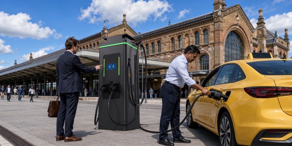
Logistics and Fleet Depots: The “Back-to-Base” Strategy: For companies operating electric delivery vans or trucks, the deployment strategy is purely functional.
- Depot Charging: Rather than using public networks, fleets build private depots. Since vans often sit idle for 8-10 hours at night, a CPO might deploy a large number of 30kW units rather than a few 240kW units.
- Opportunity Charging: For heavy-duty trucks, “pantograph” chargers or high-power MCS units are placed at loading docks. The truck charges for 15 minutes while being loaded, extending its daily range without needing a massive, heavy battery.
Public Infrastructure and Equity: Urban dwellers who live in apartments often have no place to charge at home. “Hub and Spoke” models in city centers are becoming popular, where large DCFC hubs act as the “neighborhood gas station” for apartment residents. Ensuring these are located in diverse neighborhoods is a key focus of government subsidy programs like the NEVI (National Electric Vehicle Infrastructure) program in the USA.
Chapter 9: Financial Viability: In-Depth ROI Analysis for Operators
Is an EV charging station a good investment? The answer depends on four variables: CAPEX, OPEX, Utilization, and Throughput.
CAPEX (Capital Expenditure): The upfront cost of a DCFC station is high.
- Hardware: A high-quality 120kW dual-connector charger costs between $40,000 and $75,000. A 350kW liquid-cooled unit can exceed $120,000.
- Installation: Trenching, permits, and electrical upgrades often cost as much as the hardware itself. In some urban environments, installation can reach $100,000 per stall.
- Grid Connection: If a new transformer is needed, the utility company may charge a “connection fee” ranging from $50,000 to $250,000.
OPEX (Operating Expenditure):
- Electricity Costs: CPOs pay for electricity, but they don’t just pay for the energy ($ per kWh). They also pay Demand Charges ($ per kW). If a 240kW charger is used once in a month, the CPO might be billed for that 240kW peak for the entire month, making the session extremely unprofitable.
- Maintenance: DC chargers are complex machines with filters, fans, and cooling pumps. Annual maintenance usually costs 2-3% of the hardware value.
- Software Fees: Connecting to an OCPP back-end and payment processor usually costs $20-$50 per month per connector.
Revenue Models:
- Direct Charging Fees: Usually a combination of a connection fee, a per-kWh rate, and an “idle fee” (to encourage drivers to move their car once finished).
- Advertising: Large screens on the charger can generate secondary revenue through digital-out-of-home (DOOH) ads.
- B2B Partnerships: A supermarket might pay the CPO to provide free charging to their “Gold” members.
- Grid Services: In the future, CPOs will make money by not charging. By responding to grid signals and slowing down chargers during peak demand (Demand Response), they can receive payments from the utility.
The ROI Calculation: To achieve a 5-year ROI, a typical 150kW highway charger needs a utilization rate of approximately 15-20% (about 4 to 5 hours of active charging per day). In the early years of EV adoption, many stations operate at 5% utilization, requiring government subsidies to remain solvent. As the number of EVs on the road grows, the “tipping point” for profitability is rapidly approaching in markets like California, Norway, and Eastern China.
Chapter 10: The Next Decade: 2026-2036 Technical Trend Forecast
As we peer into the future of EV charging, we see a landscape defined by three pillars: Extreme Power, Artificial Intelligence, and Grid Integration. The technology that seems cutting-edge today—240kW liquid-cooled chargers—will be the “baseline” in a decade, much as 50kW units are today.
The Rise of 800V and 1000V Architectures: By 2030, 400V systems will likely be relegated to budget, entry-level city cars. The “Gold Standard” for family and long-range EVs will be 800V or even 1000V. This transition is not just about speed; it is about efficiency. High-voltage systems reduce the amount of copper needed in the vehicle’s wiring, reducing weight and cost. For the charger, it means the ability to deliver 400kW+ of power without needing insanely thick cables. We will see the wide-scale deployment of multi-standard stacks that can seamlessly switch between 400V and 800V modes to support the mixed fleet of the 2030s.
Solid-State Batteries and the “5-Minute Charge”: The “Holy Grail” of EV technology is the solid-state battery (SSB). Unlike current liquid-electrolyte batteries, SSBs are inherently safer and can withstand much higher C-rates. Once SSBs reach mass production (expected late 2020s), we will see the emergence of Extreme Fast Charging (XFC). A car could potentially accept 500kW to 600kW of power across the entire charging curve, not just a small peak. This would reduce a full charge to under 10 minutes—finally matching the “frictionless” experience of a gasoline refill.
Wireless DC Charging: While most current wireless charging is slow AC (3kW-11kW), research into Dynamic Wireless Power Transfer (DWPT) and high-power static DC wireless pads is accelerating. Imagine a highway “charging lane” where your vehicle picks up 50kW of DC power while driving at 65mph, or a taxi stand where a cab charges at 100kW wirelessly while waiting for a passenger. This eliminates the “cabling issue”—the physical strain of heavy cables and the mechanical failure of connectors.
AI-Driven Energy Orchestration: The charging station of 2035 will not be a “dumb” power supply. It will be an AI-driven node. Using predictive analytics, the charger will know you are coming (via your car’s navigation) and will pre-calculate the most efficient charging profile based on the current grid price, the health of your battery, and your predicted departure time. If the grid is under stress, the AI might suggest a 10% slower charge in exchange for a 20% discount, all negotiated in milliseconds via the ISO 15118 protocol.
Chapter 11: Case Studies: Lessons from Global Infrastructure Rollouts
To understand how to build a successful network, we must look at the pioneers and the pitfalls of the last decade.
Norway: The Blueprint for Adoption: Norway has the highest EV penetration in the world. Their success wasn’t just due to subsidies on the cars, but a massive focus on “Charging Rights.” The government mandated that all new buildings must be EV-ready and provided grants for apartment cooperatives to install shared DC chargers.
- Key Lesson: Public-private partnerships are essential. The Norwegian government co-invested in highway fast-chargers to ensure there were no “charging deserts,” even in sparsely populated Arctic regions.
China: The Power of Scale and Standardization: China’s rollout of the GB/T standard and the state-led State Grid Corporation of China (SGCC) network has created the world’s most dense charging environment. In cities like Shenzhen, every bus and taxi is electric, supported by massive “mega-depots” featuring dozens of 120kW+ chargers.
- Key Lesson: Standardization is the ultimate efficiency tool. By forcing a single connector and a single communication protocol across the entire country, China reduced the cost of hardware through sheer volume and simplified the user experience.
North America: The “Tesla vs. The Rest” Divide: For years, the US market was split between the highly reliable Tesla Supercharger network and a fragmented, often broken, collection of third-party CCS networks. The decision by Ford, GM, and others to switch to the NACS (Tesla) connector is a tacit admission that uptime and user experience matter more than technical specifications.
- Key Lesson: A charger that is 350kW on paper is worthless if it is out of service when a driver arrives. Reliability (the “uptime” percentage) is the most important KPI for any CPO.
Chapter 12: The Regulatory Landscape and Global Subsidies
The transition to DC fast charging is not just a market phenomenon; it is a policy-driven mandate. Governments around the world are pouring billions into infrastructure to overcome the “chicken and egg” problem.
The European Green Deal and AFIR: The Alternative Fuels Infrastructure Regulation (AFIR) mandates that by 2025, there must be a fast-charging station (at least 150kW) every 60km along the EU’s main transport corridors. This regulation also forces transparency in pricing, requiring chargers to display the cost per kWh clearly, just like a gas station displays the price per liter.
The US NEVI Program: As part of the Bipartisan Infrastructure Law, the US government allocated $5 billion to the National Electric Vehicle Infrastructure (NEVI) Formula Program. To qualify for funding, a site must have at least four 150kW DC chargers, be within one mile of a highway, and maintain 97% uptime. This program is single-handedly building the “interstate highway system” of the 21st century.
Grid Codes and Interconnection Reforms: The biggest regulatory hurdle today is not money, but permitting. In many regions, it takes 18 to 24 months to get a grid connection for a high-power charging site. New regulations are being introduced to fast-track these “interconnection” requests, treating EV chargers as critical infrastructure on par with hospitals and fire stations.
Conclusion: Bridging the Gap to a Zero-Emission Future
The ultimate guide to EV DC Fast Charging reveals a technology at its inflection point. We have moved past the era of experimental prototypes and into the era of industrial-scale infrastructure. The journey from 30kW destination chargers to 240kW ultra-fast hubs, and eventually to megawatt-scale systems, is the physical manifestation of the energy transition.
For the Engineer, the challenge remains in pushing the boundaries of SiC efficiency, thermal management, and protocol security. For the Operator, the focus must shift from just “putting chargers in the ground” to ensuring 99.9% uptime and building a sustainable business model that survives the end of government subsidies. For the Policy Maker, the task is to ensure that this infrastructure is equitable, accessible, and integrated into a green, resilient power grid.
The EV DC Fast Charger is more than just a piece of hardware; it is the vital link in a new ecosystem. It turns cars into grid assets, parking lots into power plants, and long-distance travel into a zero-emission reality. As battery technology evolves and charging speeds continue to climb, the last remaining arguments against electric mobility—range anxiety and charging time—are being dismantled, one high-voltage connector at a time. The future is electric, it is direct current, and it is moving faster than ever before.
Chapter 13: Technical Analysis of Power Module Internal Architecture
To truly understand the “guts” of a DC fast charger, one must look at the Power Module. This is the fundamental building block that converts high-voltage AC from the grid into the regulated DC required by the EV. In a 240kW charger, you might find eight 30kW modules working in parallel. This modularity is the secret to both scalability and reliability.
The Rectification and PFC Stage: The first stage of a power module is the Active Rectification stage, which also performs Power Factor Correction (PFC).
- Why PFC Matters: Without PFC, a high-power charger would introduce significant harmonic distortion into the grid, overheating transformers and interfering with other electrical equipment.
- Topology: Most modern modules use a Three-Phase Vienna Rectifier or a Six-Switch Boost Rectifier. Using Silicon Carbide (SiC) MOSFETs instead of traditional Silicon IGBTs allows these rectifiers to operate at switching frequencies of 50kHz to 100kHz.
- Benefit: Higher switching frequencies mean the inductors can be smaller and lighter, and the efficiency of the PFC stage can reach 98.5%.
The Galvanic Isolation Stage: Safety is paramount. A DC charger must ensure that there is no direct electrical path between the high-voltage grid and the vehicle’s battery. This is achieved through Galvanic Isolation.
- The High-Frequency Transformer: Inside the DC-DC stage, the DC power is “chopped” back into high-frequency AC, passed through a transformer, and then rectified back into DC.
- Resonant Converters: The LLC resonant converter is the darling of the industry here. By utilizing the leakage inductance and resonant inductance of the high-frequency transformer together with an external resonant capacitor to form an LLC tank. By tuning the resonant frequency just below the switching frequency, the converter achieves Zero-Voltage Switching (ZVS) on the primary side and Zero-Current Switching (ZCS) on the secondary side.
- Why LLC Wins: Soft-switching eliminates the vast majority of switching losses, which are the dominant source of heat in a hard-switched converter. The practical payoff is enormous: the DC-DC stage routinely reaches 97-98% efficiency, runs cool enough for fully sealed enclosures, and produces the clean, low-ripple DC output that modern 800V battery management systems demand.
- Output Quality: A final LC filter stage keeps voltage ripple below 1%, protecting sensitive battery packs from the micro-cycling and harmonic heating that shorten cell life. For vehicles charging at 400V or 800V, ripple-free output also reduces the stress on the vehicle’s own DC-DC converters and cooling systems.
The Power Module as a Complete System
A modern 20kW or 30kW power module is far more than a rectifier bolted to a transformer. It is a tightly integrated system of five interacting subsystems:
- Power Stage: The PFC rectifier and LLC DC-DC converter described above, built on SiC MOSFETs for switching frequencies between 50kHz and 100kHz.
- Thermal Management: Integrated heat sinks, vapor chambers, or liquid-cooled cold plates that move heat away from the semiconductor junctions. Because every 10°C reduction in junction temperature roughly doubles semiconductor lifespan, thermal design directly determines the module’s 50,000-hour-plus MTBF.
- Control Electronics: A dedicated DSP or MCU running the control loops, plus isolated gate drivers that protect the SiC devices from over-voltage and shoot-through faults.
- Communications: An isolated CAN or RS-485 interface (and increasingly OCPP-capable Ethernet) that reports telemetry—input voltage, output current, temperatures, and fault codes—to the charger’s master controller.
- Protection Circuits: Input surge protection, output short-circuit detection, and arc-fault monitoring that shut the module down in microseconds when a fault is detected.
Why Modular Architecture Matters to You
The modular approach is what makes a 120kW or 180kW charger serviceable in the field. When one module fails, the charger detects it, derates gracefully, and continues serving vehicles at reduced power while a technician hot-swaps the failed module in minutes—no truck roll for a full-unit replacement, no site downtime measured in days. For a commercial operator, this translates directly into higher availability, lower service cost, and a charging station that keeps generating revenue even while a component is being replaced.
Key Takeaways
- The modern power module is a three-stage architecture: EMI filtering, a SiC-based PFC rectifier (Vienna or six-switch), and an LLC resonant DC-DC converter with galvanic isolation.
- Soft-switching (ZVS/ZCS) in the LLC stage is what allows 97-98% efficiency and sealed, dust-proof enclosures.
- Power factor correction above 0.99 protects the grid and avoids utility penalties, while galvanic isolation protects the vehicle.
- Modular, hot-swappable power blocks are the single biggest driver of charger uptime and serviceability in commercial deployments.
Contact MIDA Power
Understanding power module architecture is the first step to choosing hardware you can actually maintain. MIDA Power builds its 30kW to 240kW DC fast chargers around hot-swappable SiC power modules with full telemetry, so your service team can diagnose and repair failures without replacing entire units. Contact us for technical datasheets, reliability reports, and a quotation tailored to your site’s power requirements.
Post time: Aug-09-2026
