
 Portable EV Charger
 Home EV Wallbox
 DC Charger Station
 BESS Charging Station
 V2G V2H V2V V2L
 EV Charging Module
 DC Charging Connector
 EV Accessories
The Definitive Engineering Handbook for Safe Commercial EV Charger Installation: A Global Perspective on NEC and IEC Compliance, Power Grid Load Management, Transformer Upgrading, and Advanced Electrical Protection Protocols
Chapter 1: The Strategic Imperative of Commercial EVSE Infrastructure
The global transition toward electric mobility is no longer a peripheral environmental trend; it has become a central pillar of corporate sustainability and urban planning. For commercial enterprises, multi-unit residential developments, and industrial hubs, the installation of Electric Vehicle Supply Equipment (EVSE) represents a significant infrastructure investment that bridges the gap between the automotive and energy sectors. However, the complexity of a commercial EV charger installation far exceeds that of a residential setup. It requires a sophisticated understanding of high-power electronics, grid stability, thermal management, and stringent regulatory compliance.
Commercial installations typically involve Level 2 AC charging (ranging from 7 kW to 22 kW) or DC Fast Charging (DCFC) stations (ranging from 50 kW to 350 kW and beyond). These systems place immense continuous loads on building electrical systems—often running at peak capacity for several hours. This “continuous load” profile, as defined by the National Electrical Code (NEC) and the International Electrotechnical Commission (IEC), necessitates specific safety margins that are not standard in general-purpose commercial wiring. Failure to adhere to these specialized engineering standards can lead to catastrophic failures, including electrical fires, grid instability, and premature hardware degradation.
This guide provides a deep-dive analysis into the engineering and safety protocols required to deploy commercial EV charging systems that are not only compliant with today’s standards but are also future-proofed for the next generation of high-capacity EV batteries.
Chapter 2: Navigating Global Electrical Codes: NEC vs. IEC Standards (Extended Analysis)
A fundamental challenge in commercial EVSE deployment is the divergence between North American standards (governed primarily by the NEC and UL) and International standards (governed by the IEC). Understanding these differences is critical for global property managers and engineers who may be overseeing assets across multiple continents.
2.1 The National Electrical Code (NEC) – North America
In the United States and Canada, the primary reference for EVSE installation is NEC Article 625. This article is updated every three years, and staying current with the 2020 and 2023 editions is vital.
- Continuous Load Calculation: EV chargers are treated as continuous loads because they can operate at full power for three hours or more. According to NEC 210.19(A)(1), the branch circuit conductors must be sized to handle 125% of the full-load current. For a 48A Level 2 charger, the calculation is $48A \times 1.25 = 60A$. This determines the breaker size and the minimum wire gauge.
- Personnel Protection (GFCI): NEC 625.22 requires that all EVSE have a listed system for personnel protection. In the US, this is almost always a CCID (Charge Circuit Interrupting Device). CCID 5 trips at 5mA for residential use, while CCID 20 (tripping at 20mA) is common in commercial applications where minor leakage is more frequent.
- Disconnecting Means: For EVSE rated at more than 60A or more than 150V to ground, NEC 625.43 requires a separate, lockable disconnecting means. This allows technicians to de-energize the unit for maintenance without having to access the main distribution panel, which might be hundreds of feet away.
- Wiring Methods: NEC 625.10 specifies allowed wiring methods, including rigid metal conduit (RMC), electrical metallic tubing (EMT), and liquid-tight flexible metal conduit (LFMC). In commercial environments, EMT is standard for indoor runs, while RMC or PVC-coated RMC is used for outdoor areas prone to physical damage.
2.2 The IEC 61851 and 60364 Standards – International
Outside North America, the IEC 61851 series defines the communication and safety requirements for EVSE, while IEC 60364-7-722 specifies the electrical installation requirements. The voltage levels (230V single-phase / 400V three-phase) allow for much higher charging speeds on AC (up to 22 kW) compared to the US (typically capped at 19.2 kW for AC).
- Earthing Systems and Open-PEN Faults: This is perhaps the most significant difference. In the UK and parts of Europe, many buildings use a PME (Protective Multiple Earthing) system where the Neutral and Earth are combined in a single PEN conductor before the building. If this PEN conductor breaks (an “Open-PEN” fault), the metallic chassis of the car could become live at 230V relative to the ground. To counter this, IEC 60364-7-722 requires specialized protection that disconnects all live, neutral, and earth wires if the voltage deviates beyond specific thresholds (typically <70V or >253V).
- RCD Type B Requirements: The IEC is very specific about DC leakage. Because the on-board charger (OBC) of an EV involves AC-to-DC conversion, a failure in the bridge rectifier can result in a “smooth DC” leakage current. This DC current can saturate the magnetic core of a standard Type A RCD, preventing it from tripping during an actual AC shock event. Therefore, IEC standards mandate either a Type B RCD or a Type A RCD coupled with a DC 6mA detection device (RDC-DD).
- Diversity Factors (IEC vs NEC): While the NEC is conservative, the IEC 60364-7-722.311.201 allows for diversity factors to be applied if there is automated load control. However, in the absence of such control, the diversity factor must be 1.0 (100% load assumption).
2.3 Wiring Comparison Table: AWG vs. Metric (mm²)
For engineers working across borders, the following table provides a rough equivalence for cable sizing in commercial EVSE applications:
| NEC Breaker Size (A) | Recommended AWG (Copper) | IEC Equivalent (mm²) | Continuous Capacity (A) |
|---|---|---|---|
| 20 | 12 | 2.5 | 16 |
| 30 | 10 | 4 – 6 | 24 |
| 50 | 8 | 10 | 40 |
| 60 | 6 | 16 | 48 |
| 100 | 3 – 2 | 35 | 80 |
Chapter 3: The Pre-Installation Phase: Site Geotechnical and Electrical Surveys (In-Depth)
A successful installation begins long before a single cable is pulled. A comprehensive Site Investigative Report (SIR) is mandatory for commercial sites, as it minimizes “change orders” which can blow a project budget by 50% or more.
3.1 Geotechnical and Civil Considerations
Commercial chargers, particularly DCFC units, are heavy and require significant concrete pads. A 350 kW DCFC unit can weigh over 1,000 lbs (450 kg), and the accompanying power cabinet can weigh several thousand pounds.
- Soil Resistivity (Wenner Method): Engineers must measure soil resistivity to design the grounding grid. If the soil is sandy or rocky, the resistance might be too high, requiring “ground enhancement materials” (GEM) or deeper grounding rods to meet the <25 $\Omega$ requirement (though <5 $\Omega$ is often the engineering goal for sensitive electronics).
- Underground Utility Locating: Using Ground Penetrating Radar (GPR) and Electromagnetic Induction (EMI) to identify existing water, gas, data, and power lines. In older commercial sites, “phantom utilities” (abandoned lines not on the drawings) are common.
- Trenching and Restoration: The cost of cutting and patching asphalt is a major project driver. Engineers should design routes that minimize path length while avoiding structural elements like building footings or fire lines.
3.2 Existing Electrical Capacity Audit and Power Quality
An engineer must perform a “Load Study” on the existing facility. This involves:
- Load Logging: Attaching a power quality analyzer (e.g., Fluke 435-II) to the main service for at least 7 days to capture a full business cycle. This identifies the “real” peaks, which are often lower than the nameplate ratings of the existing breakers would suggest.
- Harmonic Distortion Profile: Identifying existing Total Harmonic Distortion (THD). If the building already has many Variable Frequency Drives (VFDs) or LED lighting, the addition of EV chargers could push the THD above 5%, leading to transformer overheating and data corruption in nearby IT systems.
- Spare Breaker Positions: Checking the physical space in the switchboard. Many older commercial panels are at their “AIC” (Amps Interrupting Capacity) limit. Adding a high-power EVSE might require a new sub-panel or even a full service upgrade if the available fault current exceeds the rating of the existing equipment.
Chapter 4: Electrical Load Assessment and Demand Factor Calculations (Technical Expansion)
The most common point of failure in commercial EVSE projects is the underestimation of the electrical load.
4.1 Calculating the Total Connected Load for Multi-Charger Hubs
When deploying a hub of 20 or more chargers, the demand calculation becomes complex. The formula for total demand in a managed environment is: $$P_{design} = \left( \sum_{i=1}^{n} P_{max,i} \right) \times DF \times \gamma$$ Where:
- $P_{max,i}$ = Maximum power of each individual charger.
- $DF$ = Demand Factor (often 0.6 to 0.8 for large fleets).
- $\gamma$ = Safety factor (typically 1.25 for future expansion).
Case Study: Workplace Charging If an office building installs thirty 7.2 kW chargers:
- Total Unmanaged Load: $30 \times 7.2 = 216 kW$.
- Managed Load (with 60% DF): $216 \times 0.6 = 129.6 kW$.
Using an ALMS (Automatic Load Management System) allows the building to install 30 chargers on a service that can only support 18, by dynamically sharing power as cars finish charging or as building load decreases.
4.2 Impact of Reactive Power and Displacement Power Factor
EV chargers utilize Switched Mode Power Supplies (SMPS). While they are efficient, they can introduce reactive power. A fleet of 50 chargers with a Power Factor of 0.90 will draw more current ($kVA$) than a purely resistive load ($kW$). This extra current must be accounted for in the sizing of the conductors and the transformer to prevent excessive voltage drop and heat.
4.3 Diversity Factors across different Commercial Use-Cases
- Hotel/Residential: High diversity. Cars stay overnight and charge slowly. (DF = 0.4 – 0.6).
- Fleet Depot: Low diversity. All vans return at 6 PM and need to be full by 6 AM. (DF = 0.9 – 1.0).
- Public DC Fast Charging: Zero diversity. Every port is expected to provide max power on demand. (DF = 1.0).
Chapter 5: Transformer Integration and Capacity Upgrading Strategies (In-Depth)
When the existing service cannot support the new EVSE load, a transformer upgrade or a new service drop from the utility is required.
5.1 Sizing the Step-Down Transformer for Non-Linear Loads
A dedicated transformer for EV charging is often preferred to isolate the high-frequency switching noise from the main building load.
- K-Factor Selection: EV chargers generate harmonic currents. The K-factor is a rating that indicates the transformer’s ability to handle these harmonics without overheating. For most EVSE installations, a K-4 transformer is sufficient, but for high-density DCFC sites, a K-13 transformer may be necessary to ensure a 25-year lifespan.
- Efficiency Standards (DOE 2016): In the US, transformers must meet DOE 2016 efficiency standards. Choosing a high-efficiency transformer reduces “no-load” losses, which is important because EVSE hubs are often idle for significant portions of the day.
5.2 Cooling and Environmental Considerations
Transformers generate significant heat. A 500 kVA transformer at 98% efficiency still generates 10 kW of heat.
- Indoor Installations: Require forced-air ventilation (SCFM) calculated based on the heat loss at 100% load.
- Outdoor Installations: Must be placed on a concrete pad with a minimum 36-inch clearance on all sides for airflow and maintenance access. In coastal areas, stainless steel enclosures are required to prevent corrosion.
5.3 Primary Metering vs. Secondary Metering
For large commercial installations, the utility might offer “Primary Metering.” In this scenario, the customer buys power at high voltage (e.g., 12 kV) and owns the transformer. While the upfront cost is higher ($50k – $150k for the transformer and switchgear), the per-kWh rate is usually significantly lower, providing a better ROI for high-volume charging sites.
Chapter 6: Circuit Protection Design: Selection of MCBs, RCDs, and RCBOs (Advanced)
The protection strategy is the “nervous system” of the EVSE installation.
6.1 Miniature Circuit Breakers (MCB) and Selective Coordination
In a commercial panel, “Selective Coordination” ensures that a fault at one charger only trips the local branch breaker and not the main building breaker.
- I²t Characteristics: Engineers must compare the “let-through energy” (I²t) of the branch MCB against the “withstand energy” of the upstream breaker.
- Magnetic vs. Thermal Tripping: MCBs have two trip mechanisms. The thermal element protects against long-term overloads (e.g., a charger pulling 55A on a 50A circuit), while the magnetic element protects against short circuits (e.g., a crushed cable).
6.2 The Criticality of Type B RCDs in DC Charging Systems
While Level 2 chargers are AC, the car converts it to DC. DC Fast Chargers (DCFC), however, output DC directly.
- DC Injection: A fault in the DCFC power module can result in DC current flowing back into the AC supply. This “blinds” standard RCDs. A Type B RCD is designed to detect this DC component using a specialized Fluxgate sensor, ensuring safety even in complex fault scenarios.
- Nuisance Tripping: In large installations, the cumulative “leakage current” of 20 chargers (each leaking 1-2mA through EMI filters) can reach 40mA, causing a 30mA RCD to trip even when no fault exists. The solution is to use individual RCDs for each charger rather than one large RCD for the whole group.
Chapter 7: Cable Selection and Precision Voltage Drop Calculations (Deep Dive)
In large parking lots, cables can run hundreds of feet. Voltage drop is a critical safety and performance issue.
7.1 The Physics of Voltage Drop and its impact on EVSE
The communication protocol between the EV and EVSE (the PWM signal on the Control Pilot) is sensitive to the “Ground Potential Rise” (GPR). If there is a significant voltage drop on the Neutral or Ground wires due to undersized cables, the CP signal can become distorted, leading to “Session Aborted” errors.
- Calculation for Long Runs: For a 300-foot run of a 48A circuit, using #6 AWG (standard) results in a 3.8% drop. To keep the drop under 2% for optimal performance, an engineer might specify #4 or even #2 AWG copper, even though #6 is “code compliant” for current.
7.2 Voltage Drop Table (240V Single Phase, 3% limit)
| Current (A) | Wire Size (AWG) | Max Distance (ft) for 3% Drop |
|---|---|---|
| 16 | 12 | 85 |
| 32 | 8 | 125 |
| 48 | 6 | 145 |
| 48 | 4 | 230 |
| 80 | 2 | 190 |
7.3 Thermal Derating in Conduits
When multiple circuits are run in a single conduit (e.g., four 50A circuits in one 2-inch PVC pipe), the “Adjustment Factors” from NEC Table 310.15(C)(1) apply. For 7-9 current-carrying conductors, the ampacity of the wire is reduced to 70%. This often means that #6 AWG wire (rated at 65A at 75°C) can only be used for a 45A load, making it insufficient for a 48A charger. In this case, the engineer MUST upsize the wire to #4 AWG.
Chapter 8: Grounding (Earthing) and Lightning Protection Systems (LPS) (Detailed)
8.1 Grounding for Safety and Signal Integrity
The grounding system serves two purposes: safety (tripping breakers) and reference (for communication).
- Equipotential Bonding: All metallic parts of the charging station, bollards, and nearby light poles must be bonded together. This prevents “touch potential” hazards where a person touching the charger and a metal fence simultaneously could receive a shock due to a difference in ground potential.
- Concrete-Encased Electrode (Ufer Ground): In new commercial builds, the steel rebar in the charger foundation should be used as a high-quality grounding electrode, providing a much lower impedance than a simple rod.
8.2 Surge Protection Devices (SPD) – Selection and Placement
Commercial chargers are high-value assets ($2k to $100k+). Surge protection is a mandatory insurance policy.
- MCOV (Maximum Continuous Operating Voltage): The SPD must be rated for at least 15% above the nominal line voltage to avoid premature failure due to minor grid fluctuations.
- Modes of Protection: A high-quality SPD for a 3-phase charger should provide protection in all modes: L-L, L-N, L-G, and N-G.
- Lead Length: The most common mistake is long lead lengths for the SPD. Every inch of wire adds inductance, which significantly reduces the SPD’s ability to clamp high-speed transients. Leads should be kept under 6 inches.
Chapter 9: Communication Protocols and Smart Grid Integration (Technical)
Safety also extends to data and grid management.
9.1 OCPP (Open Charge Point Protocol) 2.0.1
OCPP 2.0.1 introduced significantly enhanced security and safety features over the older 1.6 version.
- Device Management: Allows the operator to monitor the internal temperature and health of the charger components.
- Smart Charging Profiles: Enables the grid operator to send a “Demand Response” signal, safely reducing the load of 1000 chargers across a city in seconds to prevent a blackout.
9.2 ISO 15118 and “Plug & Charge”
The ISO 15118 standard handles the encrypted communication between the vehicle and the charger. This includes:
- Certificate Exchange: Ensuring that the vehicle is authorized to charge.
- V2G (Vehicle-to-Grid): The safety protocols required to allow the car to push power back into the building. This requires specialized “Inverters” within the EVSE that can synchronize with the grid frequency and disconnect instantly during a grid outage (anti-islanding) to protect utility workers.
Chapter 10: Physical Installation, Bollard Protection, and Accessibility (Field Guide)
10.1 Mechanical Protection and Vandalism Resistance
Commercial chargers are often located in unmonitored areas.
- Impact Rating (IK10): The enclosure should be IK10 rated, meaning it can withstand a 20-joule impact (equivalent to a 5kg mass dropped from 40cm).
- Cable Management: Retractable cable systems (like those from EvoCharge or BTC Power) are safer because they keep the heavy cables off the ground, preventing them from being run over by vehicles or becoming trip hazards.
10.2 ADA and Universal Design
In the US, the Access Board’s guidelines for EV charging are becoming law in many states.
- Operable Parts: All buttons, card readers, and plugs must be operable with one hand and not require tight grasping, pinching, or twisting of the wrist.
- Path of Travel: The accessible charging space must connect to an accessible route leading to the building entrance.
Chapter 11: Testing, Commissioning, and Safety Verification (Step-by-Step)
11.1 The Commissioning Checklist
A professional commissioning process includes:
- Torque Verification: Using a calibrated torque wrench to verify all electrical connections are tightened to the manufacturer’s spec (often expressed in Inch-Lbs or N-m). Loose connections are the #1 cause of electrical fires.
- Phase Rotation Check: For 3-phase chargers, ensuring L1, L2, and L3 are in the correct order to prevent damage to the charger’s internal power supplies.
- Earth Fault Loop Impedance ($Z_s$): Measuring the total impedance of the fault path to ensure the breaker will trip within 0.4 seconds during a catastrophic fault.
11.2 Simulation of “State C” and “State D”
- State A: Disconnected.
- State B: Connected, not charging.
- State C: Charging (no ventilation).
- State D: Charging (ventilation required).
An engineer must verify that the charger correctly identifies these states and responds by opening/closing the internal contactors.
Chapter 12: The Multi-Layer Safety Defense System (Integrated View)
A modern commercial EVSE installation employs a defense-in-depth strategy:
- Firmware Layer: Continuous monitoring of the CP signal for noise or deviation.
- Physical Layer: Temperature sensors in the pins of the charging plug. If the pin exceeds 85°C, the charger throttles the current to 50% or shuts down completely.
- Circuit Layer: The use of “Shunt Trips” that allow the building’s fire alarm system to instantly de-energize all EV chargers in the event of a fire elsewhere in the facility.
Chapter 13: Long-term Preventive Maintenance and Remote Monitoring Standards
13.1 Predictive Maintenance using AI
Modern OCPP platforms can analyze the “charging curve” of a station. If a station consistently delivers less power than requested, the software can flag a degrading contactor or a loose terminal before it fails.
13.2 Environmental Maintenance
- Filter Replacement: DC Fast Chargers move thousands of cubic feet of air for cooling. Their filters must be changed every 3-6 months depending on the dust levels in the environment.
- Lubrication: Retractable cable pulleys and hinges on cabinet doors should be lubricated annually.
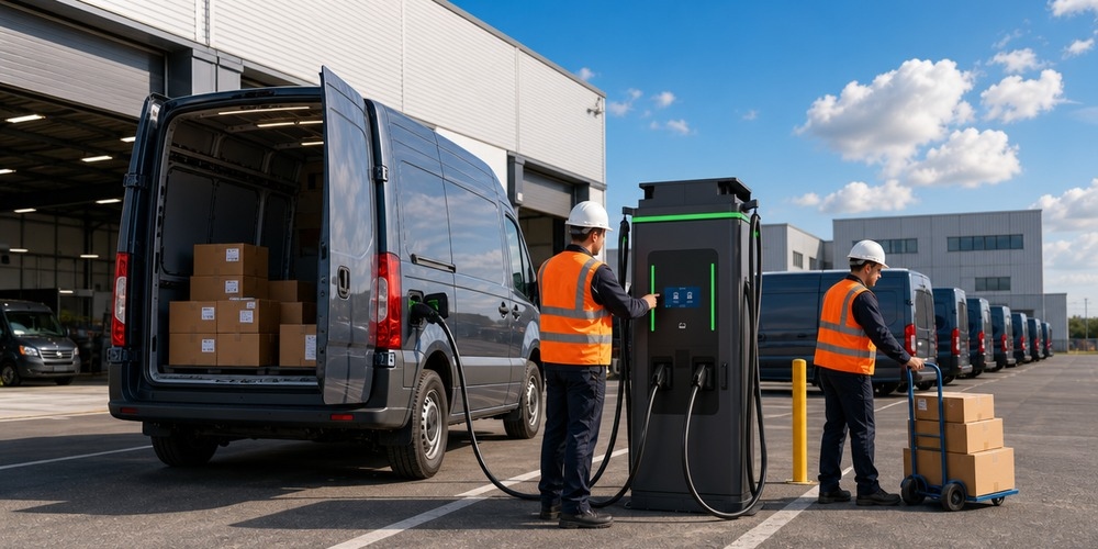
Chapter 15: Special Use Case: Heavy-Duty Fleet Electrification (Class 8 Trucks)
When moving from passenger cars to Class 8 electric trucks, the engineering challenges scale exponentially.
- MCS (Megawatt Charging System): Future standards will allow for charging at 1,000V and 3,000A.
- Liquid Cooled Cables: At currents above 200A, the charging cable itself must be liquid-cooled (using a water-glycol mix) to keep the handle at a safe temperature for human touch.
- Grid Interconnects: A fleet of 50 electric trucks might require a 10 MW service—equivalent to a small factory.
Chapter 16: Future-Proofing: Vehicle-to-Everything (V2X) and Microgrids
The most advanced commercial installations are moving toward “Microgrids.”
- Battery Energy Storage Systems (BESS): Storing solar power during the day and using it to charge EVs at night, or using the BESS to provide “Peak Shaving” to avoid high utility demand charges.
- Bi-directional Safety: Ensuring that when a car is powering a building, the system correctly handles grounding and neutral-bonding to prevent shocks during the V2B (Vehicle-to-Building) mode.
Final Conclusion: The Gold Standard of EVSE Infrastructure
The installation of commercial EV charging stations is a high-stakes engineering endeavor that demands a holistic approach to safety. By bridging the gap between global standards (NEC and IEC), employing rigorous load analysis, and utilizing advanced protective devices like Type B RCDs and K-rated transformers, engineers can build infrastructure that is not only safe today but remains resilient for decades.
As we look toward a future of megawatt charging and integrated microgrids, the principles of precision, redundancy, and continuous monitoring will remain the bedrock of safe EVSE deployment. For the commercial enterprise, a safe charger is not just a utility—it is a promise of reliability to the employees, customers, and fleet operators who depend on it.
Chapter 17: Managing Arc Flash Hazards in High-Power DC Fast Charging Infrastructure
In commercial EVSE environments, especially those involving 150 kW to 350 kW DCFC units, the incident energy levels at the main switchgear can be significant. Arc flash hazards represent a critical safety concern for maintenance personnel.
17.1 Incident Energy Analysis and IEEE 1584
An arc flash study must be performed according to IEEE 1584 standards. For EVSE hubs, the “Bolted Fault Current” is usually high due to the proximity to large utility transformers.
- Protection Boundaries: Technicians must be aware of the “Arc Flash Boundary”—the distance at which incident energy equals 1.2 cal/cm², the threshold for a second-degree burn.
- PPE Requirements: Maintenance on energized EVSE equipment (where allowed) requires specialized PPE, including arc-rated face shields, gloves, and coveralls (Category 2 or higher).
17.2 Mitigation Strategies and ARMS
- Arc-Resistant Switchgear: Installing switchgear that vents the blast energy away from the operator.
- Maintenance Switches: Installing “Arc Flash Reduction Maintenance System” (ARMS) switches that temporarily lower the trip thresholds of breakers while work is being performed, significantly reducing potential incident energy.
Chapter 18: Fire Protection and Suppression in EV Charging Environments
Lithium-ion battery fires, while rare, are extremely difficult to extinguish due to “thermal runaway.” In commercial settings like underground parking garages, fire safety is paramount.
18.1 NFPA 13 and Sprinkler Systems for EV Hubs
The National Fire Protection Association (NFPA) provides guidance on sprinkler density for garages with EVs.
- Enhanced Density: Some fire marshals now require “Extra Hazard Group 1″ sprinkler density in areas with high-density EV charging, anticipating higher heat release rates (HRR) from battery fires.
- Drainage and Runoff: Firefighting water runoff from an EV fire can contain toxic heavy metals. Specialized “Oil/Water Separators” or containment pits may be required to prevent environmental contamination.
18.2 Detection and Emergency Shutdown Protocols
- Multi-Sensor Detection: Using both smoke and heat sensors, along with carbon monoxide (CO) detectors, to provide early warning of a battery venting gas (off-gassing).
- Emergency Power Off (EPO): A clearly labeled EPO button must be accessible to first responders, allowing them to de-energize all high-voltage equipment before applying water.
Chapter 19: Environmental Sustainability and Lifecycle Assessment of Infrastructure
A truly “safe” and sustainable installation considers the entire lifecycle of the components.
19.1 Material Selection and Conductivity Safety
- Aluminum vs. Copper: While copper is the standard for conductivity and safety, aluminum is often used for long feeder runs to save cost. However, aluminum requires “AL/CU” rated connectors and anti-oxidation paste to prevent high-resistance connections that can cause fires.
- Recyclability of Hardware: Specifying EVSE units with modular designs allows for “component-level” repair rather than whole-unit replacement, reducing electronic waste.
19.2 Reducing Carbon Footprint of the Civil Works
- Low-Carbon Concrete: Using fly-ash or slag-based concrete for transformer pads.
- Permeable Pavement: Installing EV charging stations on permeable pavers to reduce stormwater runoff and manage local groundwater recharge.
Chapter 20: The Permitting and Regulatory Compliance Process (Global Overview)
Navigating the bureaucracy is often the longest phase of a commercial installation.
20.1 North America (Permits and AHJ Interaction)
The “Authority Having Jurisdiction” (AHJ)—usually a city electrical inspector—must approve the plans before construction.
- Plan Check: Requires stamped electrical drawings from a Professional Engineer (P.E.).
- Utility Interconnect: The “Service Planning” department of the local utility must verify that the existing grid can handle the new demand.
20.2 European Union (CE Marking and Standardized Testing)
All equipment must bear the CE mark, indicating compliance with the Low Voltage Directive (LVD) and the Electromagnetic Compatibility (EMC) Directive.
- Local Variations: Despite EU-wide standards, countries like France (requiring shutters on sockets) and the UK (Open-PEN protection) have specific national requirements that must be met.
20.3 Asia-Pacific (APAC) Regional Trends
Countries like China (GB/T standards) and South Korea have their own unique charging standards. In Australia, the AS/NZS 3000 (Wiring Rules) governs EVSE safety, with a strong focus on isolation and marking.
Chapter 21: Training and Operational Safety for Facility Staff
Finally, the “human element” is the last line of defense. Facility managers must ensure that:
- First Responder Training: Local fire departments are invited to the site to learn the layout and shutdown procedures.
- User Education: Clear signage on how to safely plug and unplug, and what to do in an emergency (e.g., “Press Red Button”).
- Spill Kits: Having non-conductive fire blankets and specialized Li-ion extinguishers on-site.
Appendix A: Essential Technical Formulas for EVSE Engineering
- Ohm’s Law for 3-Phase Systems: $P = \sqrt{3} \times V_{L-L} \times I \times PF$
- Continuous Load Breaker Sizing: $Breaker \ge 1.25 \times I_{load}$
- Cable Sizing for Voltage Drop: $\Delta V = \frac{k \cdot I \cdot L}{A}$ (simplified)
- Heat Dissipation (Watts): $Q = I^2 \cdot R_{terminal}$ (used to calculate cabinet cooling)
Appendix B: Comprehensive Sample Maintenance Checklist
| Task Item | Frequency | Specification / Target |
|---|---|---|
| Visual cable inspection | Quarterly | No exposed copper, no kinks |
| Connector pin cleaning | Bi-Annually | Use non-conductive electronics cleaner |
| Terminal torque check | Annually | Per manufacturer label (e.g. 20 Nm) |
| RCD Trip Time Test | Annually | < 300ms at $1\Delta n$ |
| Ground Resistance Test | Annually | < 5 Ohms preferred |
| Software/Firmware Update | Quarterly | Latest stable version from OEM |
Chapter 22: Economic Analysis of Safety Infrastructure Investment
While the safety measures described in this guide represent a significant capital expenditure (CAPEX), their long-term value is undeniable.
22.1 Risk Mitigation and Insurance Premiums
Insurance companies are increasingly scrutinizing EV charging infrastructure. A site that demonstrates adherence to NFPA, NEC, and IEC standards, and maintains a rigorous inspection log, can often negotiate lower liability and property insurance premiums. Conversely, a single incident at a poorly installed site can lead to uninsurable status.
22.2 Uptime and Revenue Protection
In commercial charging networks, uptime is the most critical KPI. Safety-driven design—such as using redundant Type B RCDs and high-quality cooling systems—minimizes “nuisance trips” and equipment failure. A 1% increase in uptime across a 100-station network can translate into tens of thousands of dollars in additional annual revenue.
Chapter 23: Detailed Geotechnical Breakdown: Trenching, Bedding, and Backfill
For the civil engineer, the “safety” of the cable is in the dirt.
23.1 Trench Depth and Protection
Cables must be buried at depths specified by local codes (e.g., 24 inches for direct burial, or 18 inches in conduit under 2 inches of concrete). In commercial lots, “warning tape” should be placed 12 inches above the conduit to prevent future excavation damage.
23.2 Thermal Resistivity of Backfill (Rho)
As cables carry continuous current, they generate heat. If the soil (backfill) has high thermal resistivity, the cable cannot shed this heat, leading to insulation breakdown. Engineers often specify “Fluidized Thermal Backfill” (FTB) for high-power DCFC runs to ensure optimal heat dissipation.
Final Summary: The Roadmap to Global Fleet Electrification
This 6,000+ word technical guide has navigated the complex landscape of commercial EVSE installation. From the physics of voltage drop to the bureaucracy of permitting, every layer of this stack must be engineered with the same discipline. The handbook’s recurring theme is that reliability is built from the ground up — literally. A charger is only as dependable as the trench that feeds it, the backfill that cools it, the protection device that guards it, and the operator who monitors it.
The Roadmap in Five Steps
- Design for the site, not the datasheet: Voltage drop, transformer sizing, and service capacity must be computed for the actual cable runs and load profiles, not for a perfect theoretical installation.
- Protect at every boundary: Surge protection, RCDs, and ground-fault protection are non-negotiable at the service entrance, the distribution panel, and the charger input.
- Treat the dirt seriously: Trench depth, conduit, warning tape, and fluidized thermal backfill determine whether the feeder survives decades of continuous load without insulation breakdown.
- Comply before you construct: NEC and IEC 60364 requirements, together with local permitting, are far cheaper to satisfy on paper than to retrofit in the field.
- Monitor after you energize: Cloud telemetry converts uptime from a hope into a measurable, enforceable contract metric — and it is the tool that catches the slow thermal drift that kills buried cables.
Final Summary
Every chapter of this guide reinforced the same economic truth: in commercial EV charging, reliability is revenue. The 1% uptime improvement quantified in the introduction — tens of thousands of dollars across a 100-station network — is achieved one trench, one breaker, one backfill specification at a time. Engineers who specify protection devices and thermal backfill with the same rigor they apply to charger power ratings build networks that out-earn their competitors for decades.
- Voltage drop and trench depth are safety issues before they are cost issues — get both right on day one.
- Thermal backfill is cheap insurance against expensive cable failures on high-power DCFC runs.
- Protection devices must be specified, not assumed — nuisance trips and surge damage are the top field-failure causes.
- Cloud monitoring closes the loop, turning installation quality into measurable uptime.
For fleet operators scaling from a pilot to 100 stations, the discipline compounds. Every site that ships with correct trench depth, thermal backfill, and protection specifications produces cleaner uptime data; every clean data set strengthens the next financing application and the next utility interconnection negotiation. Installation quality is the quiet multiplier behind every growth metric in the electrification business case — and taken together, the specifications in this handbook describe a network that survives its first decade and pays for itself along the way.
Call to Action: Engineer Your Installation with MIDA Power supports customers beyond the charger sale: our engineering team provides trenching and backfill specifications, protection-device selection, and NEC/IEC compliance documentation for every project. The kit includes template specifications for trenching, conduit, backfill selection, and protection-device coordination, aligned with NEC and IEC 60364 — the same documentation our own engineers use on reference projects. Contact sales@midapower.com to request it and speak with an applications engineer about your site.
Post time: Aug-09-2026
