
 Portable EV Charger
 Home EV Wallbox
 DC Charger Station
 BESS Charging Station
 V2G V2H V2V V2L
 EV Charging Module
 DC Charging Connector
 EV Accessories
title: “High Voltage Trend: DC Charging Enters the 1000V Era” slug: “high-voltage-trend-dc-charging-1000v-era” meta_description: “Why 1000V is the new standard for DC fast charging: 800V/900V vehicle platforms, IEC 61851-23:2023 compliance, SiC power modules, insulation monitoring and liquid-cooled 600kW+ stations explained.” keywords: ["1000V DC fast charging", "800V EV charging", "IEC 61851-23:2023", "SiC power module", "insulation monitoring", "liquid-cooled charging station", "HPC charging"]
Introduction
The 1000V DC bus has become the defining architecture of next-generation electric vehicle charging: by 2026, every high-power charging (HPC) station designed for 350kW and above is built around 1000V output capability, and the revised IEC 61851-23:2023 standard now codifies the engineering requirements — insulation monitoring, liquid-cooling safety, and bidirectional power transfer — that make this voltage shift safe, efficient, and interoperable. The trigger is on the vehicle side: after Porsche’s 800V Taycan in 2019 and Hyundai’s E-GMP platform in 2021, the majority of new long-range EVs launched since 2024 — from Lucid’s 900V+ architecture to dozens of 800V models from Asian and Western OEMs — now charge natively on 800V or higher. A charger locked to a 400V architecture cannot unlock their peak charging curve, which means slower throughput, longer queues, and stranded capital for operators.
Raising the DC bus voltage is not a marginal optimization; it is the only economically sustainable way to push charging power beyond 350kW. Because power equals voltage multiplied by current (P = V × I), a 1000V system delivers 600kW at just 600A, whereas a 400V system would need 1,500A for the same result — a current level that exceeds the physical limits of practical cable weight, connector thermals, and grid-side conductor economics. Every serious CPO, highway operator, and fleet manager evaluating new infrastructure in 2026 is therefore asking the same question: is my next station 1000V-ready? This article explains the physics, the standard, and the component-level technology (SiC modules, insulation monitoring, liquid cooling) that make the 1000V era commercially viable — and how MIDA’s 150V–1000V charging portfolio future-proofs the investment.
Key Takeaways
- 1000V is the new ceiling for DC fast charging economics. At the same 600A cable rating, a 1000V bus delivers 600kW versus 240kW at 400V — more than 2.5× the throughput with identical thermal constraints.
- Voltage, not current, is the scaling lever. Doubling the bus voltage halves the current for the same power, cutting cable I²R losses by roughly 75% and eliminating the need for impossibly heavy 1,000A+ cables.
- Wide-output chargers (150V–1000V) are mandatory for fleet compatibility. A single 1000V-capable station serves legacy 400V vehicles and new 800V/900V platforms alike, protecting the CPO’s hardware investment as the fleet mix transitions.
- IEC 61851-23:2023 makes 1000V operation a compliance matter. The 2023 edition requires self-testing insulation monitoring with dynamic response, liquid-cooling safety per IEC 62196-3:2022 for 350kW+ systems, and anti-islanding provisions for bidirectional (BPT/V2G) operation.
- SiC power modules are the efficiency engine of 1000V charging. Silicon-carbide MOSFET-based modules sustain peak conversion efficiency above 96.5%, turning the voltage upgrade directly into lower energy losses and lower total cost of ownership (TCO).
- Insulation monitoring is the safety backbone of a 1000V system. Millisecond-level insulation-resistance detection between the DC bus and ground is a mandatory self-test feature — not an optional accessory — under the updated standard.
- MIDA’s 1000V-ready ecosystem is production-verified. Liquid-cooled power modules (40–125kW), 600A/1000V liquid-cooled connectors, and stations from 360kW to 1,680kW with 150V–1000V output cover the full hardware stack required for HPC deployment.
Deep Dive: The Engineering Behind the 1000V Era
1. Why 1000V? The Physics of High-Speed Charging
The case for high-voltage charging reduces to one equation: P = V × I. A 400V charger delivering 350kW must sustain roughly 875A of DC current — a figure that forces liquid-cooled cables, premium connectors, and severe thermal management across the entire power path. A 1000V charger achieves the same 350kW at just 350A, and stretches to 600kW at 600A, which is precisely the rating of today’s generation of liquid-cooled high-power connectors. In short, raising the bus voltage multiplies station capacity without multiplying the physical size, weight, or heat of the charging equipment.
The loss reduction is equally decisive. Cable and conductor losses scale with the square of current (I²R), so delivering 500kW at 1000V (500A) generates roughly one-quarter of the conductor heat of delivering the same 500kW at 500V (1,000A). Across a station operating 10–14 hours per day, that difference compounds into meaningful electricity savings, smaller upstream transformers, and lower grid-connection costs — the three largest line items in a site’s total cost of ownership.
| Parameter | 400V system | 800V system | 1000V system |
|---|---|---|---|
| Max power at 600A | 240 kW | 480 kW | 600 kW |
| Current needed for 350kW | ~875 A | ~438 A | ~350 A |
| Cable I²R losses (relative) | 4× baseline | 1× baseline | ~0.6× baseline |
| Typical 10–80% SoC time (100kWh pack) | 35–45 min | 16–20 min | 9–12 min |
| Liquid cooling required above 350kW | Yes (marginal) | Yes (standard) | Yes (standard, per IEC 62196-3) |
The vehicle side is already there. 800V battery architectures have moved from premium flagships to the mass market: Hyundai’s E-GMP platform (Ioniq 5/6, EV6) charges 10–80% in roughly 18 minutes on 350kW hardware, Tesla’s Cybertruck introduced an 800V architecture to the NACS ecosystem, and Lucid has pushed system voltage past 900V. Chinese OEMs have made 800V a standard feature across mid-priced segments since 2023, and the NACS specification itself supports DC charging up to 1000V. Industry forecasts consistently show the 800V+ share of new BEV sales climbing through the second half of this decade, which means charging networks that cannot deliver 800–1000V output will increasingly bottleneck the vehicles that matter most to throughput.
For operators, the commercial argument is throughput. A 1000V-capable station with intelligent dual-gun power sharing can serve an 800V EV at full power while simultaneously topping up a 400V taxi at a lower branch current — turning one power cabinet into two revenue streams. This is why leading 1000V liquid-cooled ultra-fast charging stations are engineered with 150V–1000V wide output ranges and dynamic power allocation rather than fixed voltage rails.
2. SiC Power Modules and the Thermal Architecture of 1000V Chargers
The component that makes 1000V practical inside the cabinet is the silicon-carbide (SiC) power module. Compared with conventional silicon IGBTs, SiC MOSFETs switch at higher frequencies with dramatically lower conduction and switching losses, tolerate junction temperatures up to 200°C, and maintain efficiency across a wide 150V–1000V output window. The result at system level is a peak conversion efficiency above 96.5% at full load — a figure that directly reduces the operator’s electricity bill and the heat that the cabinet must reject.
Module-level design is where the 1000V claim is won or lost. A station rated for 360kW typically pairs twelve 30kW modules or six 60kW modules behind a shared controller, with DC-DC topologies that regulate a 1000V input bus down to the exact voltage the vehicle requests during the handshake. MIDA’s liquid-cooled EV charging power modules span 20kW–60kW standard air-cooled units, 40kW–125kW liquid-cooled units for high-power cabinets, and 30kW–62.5kW bidirectional units for V2G-ready sites. The 1000V DC-DC variants are engineered specifically for high-voltage bus architectures, with isolated, dust-proof designs that keep the electronics sealed from the environment.
Thermal management separates industrial-grade hardware from low-cost commodity chargers. At 600A continuous output, a 1000V system must reject several kilowatts of heat from cables, connectors, and modules simultaneously:
- Liquid-cooled power modules route coolant through dedicated cold plates, holding junction temperatures stable under sustained peak load. MIDA’s IP65-rated isolated air-duct modules additionally prevent dust, moisture, and salt fog from contacting the circuit board, yielding an MTTF above 500,000 hours and eliminating most preventive maintenance dispatches.
- Liquid-cooled cables and connectors are mandatory above roughly 350A continuous. MIDA’s 600A liquid-cooled charging connectors rated for 1000V circulate coolant through the cable jacket and connector head, keeping handle weight manageable and temperature rise within IEC 62196-3:2022 limits even during back-to-back 600kW sessions.
- System-level heat rejection follows an intelligent priority: modules derate gracefully only when internal temperature sensors report sustained overload, preserving uptime instead of tripping.
This is the architecture behind the current generation of 350kW HPC stations with liquid-cooled connectors, and it scales linearly: the same modular, liquid-cooled platform extends to 600kW–1,080kW liquid-cooled stations and 360kW–1,680kW split-type cabinets for truck and fleet corridors.
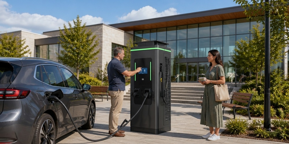
3. IEC 61851-23:2023, Insulation Monitoring, and Vehicle Compatibility
The 2023 revision of IEC 61851-23 is the compliance watershed for high-voltage charging. Where the earlier edition effectively governed 750V-class equipment, the 2023 edition was written for the 1000V era and now mandates three engineering pillars:
- 1000V+ system support. DC charging equipment must safely cover next-generation high-voltage platforms, with insulation monitoring (IMD) that performs a power-on self-test and responds dynamically — measuring insulation resistance between the DC bus and protective earth in real time and opening the contactors within milliseconds if a fault is detected. This is a hard requirement, not an optional feature, because a 1000V bus presents far greater shock and arc-flash energy than legacy 400V equipment.
- Liquid-cooling safety per IEC 62196-3:2022. For 350kW+ systems, the standard requires active monitoring of the liquid-cooling loop — coolant pressure, flow, and temperature rise — with automatic derating or shutdown if the loop degrades. Connector and cable temperature sensing is integrated so that a failing cable cannot melt or arc before the controller intervenes.
- Bidirectional power transfer (BPT) provisions. Stations supporting V2G/V2H must satisfy the annex on grid-connection safety and anti-islanding, ensuring that a charger feeding energy back to the grid disconnects cleanly during a utility outage. Protocols follow ISO 15118-20:2022 for Plug & Charge and bidirectional communication, alongside DIN 70121 for CCS sessions.
Insulation monitoring deserves special attention because it is the difference between a well-engineered 1000V station and a liability. In normal operation, the DC bus is isolated from ground; a single insulation fault — from coolant ingress, cable abrasion, or connector moisture — creates a path for current that can energize the vehicle chassis or station enclosure. A compliant IMD continuously measures insulation resistance, runs a self-check at every power-on, and coordinates with the station controller to terminate the session safely. Combined with Type A + 6mA DC residual current protection and mandatory installation practices (protective earth resistance below 4Ω, upstream breakers rated at 1.2× or more of the station’s nominal power, and cable up-sizing when the distribution run exceeds 300 meters), the 1000V station is engineered to fail safe.
Vehicle compatibility is the final pillar, and it is broader than voltage. A 1000V station must talk to every vehicle generation through the charging-session protocol stack: the CP/PP analog handshake, the digital handshake (ISO 15118 or DIN 70121), and the network layer (OCPP 1.6J or 2.0.1) that connects the station to the CPO’s backend. Connector coverage is equally critical — CCS1 for North America, CCS2 for Europe and most of Asia, NACS for the Tesla ecosystem, CHAdeMO for legacy Japanese vehicles, and GBT for the Chinese domestic market. MIDA’s stations ship with swappable connector architectures and the full protocol stack, so a single 150V–1000V cabinet can serve a mixed fleet of 400V, 800V, and 900V vehicles regardless of regional standard. The high-voltage era also pairs naturally with energy storage: pairing a 1000V charger with a BESS buffers peak demand charges, which is why integrated ESS charging solutions are increasingly bundled into highway and fleet sites.
FAQ
1. Will a 1000V DC fast charger damage my 400V EV?
No. A compliant 1000V station operates over a wide 150V–1000V output window and negotiates the exact charging voltage with the vehicle during the handshake, so a 400V car receives a 400V-level session. The station’s power modules regulate output dynamically to match the vehicle’s request; the 1000V rating simply defines the upper ceiling, not the session voltage.
2. How much faster does an 800V vehicle actually charge on a 1000V station?
An 800V EV charges roughly twice as fast as the same battery on 400V hardware, and a 1000V-capable station lets it hold peak power longer. As a rule of thumb, a 100kWh pack on an 800V architecture completes a 10–80% session in 16–20 minutes on a 350kW unit, and in roughly 9–12 minutes on a 600kW-class unit — versus 35–45 minutes on a 400V, 150kW charger.
3. What does IEC 61851-23:2023 require for 1000V charging stations?
The 2023 edition mandates 1000V+ system capability, insulation monitoring with power-on self-test and dynamic fault response, liquid-cooling loop safety (pressure, flow, and temperature monitoring) per IEC 62196-3:2022 for high-power systems, and anti-islanding provisions for bidirectional (BPT/V2G) operation. Any new HPC station targeting the European market should be verified against these requirements.
4. Why are SiC power modules important for 1000V charging?
SiC MOSFETs switch faster and lose far less energy than silicon IGBTs at high voltage, enabling peak conversion efficiency above 96.5% across a 150V–1000V output range. Higher efficiency means less waste heat to remove, smaller and quieter cooling systems, and lower electricity losses — which directly improves the station’s TCO over a 10-year operating life.
5. Is liquid cooling mandatory for charging stations above 350kW?
Effectively, yes. Sustained currents above roughly 350A generate heat that air-cooled cables and connectors cannot reject within connector temperature limits, and IEC 62196-3:2022 requires active monitoring of the liquid-cooling loop at high power. Liquid-cooled power modules and cables are also what keep a 600kW station compact, reliable, and safe under back-to-back heavy sessions.
6. How does insulation monitoring protect a 1000V charging system?
Insulation monitoring continuously measures the insulation resistance between the DC bus and ground and performs a self-test at every power-on. If a fault develops — from coolant ingress, cable damage, or moisture in a connector — the monitoring unit detects it in milliseconds and commands the station to open the contactors, preventing chassis energization and arc events on a 1000V bus where fault energy is substantially higher than at 400V.
7. Can one 1000V station serve all connector standards and vehicle generations?
Yes. A single 1000V station can be equipped with CCS1, CCS2, NACS, CHAdeMO, or GBT connectors and supports both 400V legacy vehicles and 800V/900V platforms through its wide output range and protocol stack (ISO 15118 Plug & Charge, DIN 70121, OCPP 1.6J/2.0.1). This universal compatibility is exactly why 150V–1000V wide-output cabinets are the recommended architecture for CPOs future-proofing their networks.
Post time: Aug-14-2026
