
 Portable EV Charger
 Home EV Wallbox
 DC Charger Station
 BESS Charging Station
 V2G V2H V2V V2L
 EV Charging Module
 DC Charging Connector
 EV Accessories
Deciphering the Global Charging Paradox: A Multi-Dimensional Technical Deep Dive into CCS1 vs. CCS2 Standards, Physical Layer Communication Protocols, Insulation Monitoring Architectures, and the Geopolitical Shift Toward NACS Integration
Chapter 1: Introduction: The Landscape of Global Electrification and the Standard War
The global automotive industry is currently navigating one of the most significant technological pivots in its century-long history: the transition from internal combustion engines (ICE) to electric vehicles (EV). While the chemistry of lithium-ion batteries and the efficiency of silicon carbide (SiC) inverters often capture the headlines, the unsung hero—and frequent bottleneck—of this revolution is the charging interface.
The charging standard is the umbilical cord of the EV ecosystem. It is not merely a plug and a socket; it is a sophisticated system of high-voltage power electronics, digital communication protocols, and safety interlocks. Today, the world is primarily divided into two camps of the Combined Charging System (CCS): CCS1 (Common in North America and Korea) and CCS2 (Common in Europe and most other regions).
However, this binary divide is being disrupted. The rise of the North American Charging Standard (NACS), recently codified as SAE J3400, has sent shockwaves through the industry, threatening to render CCS1 obsolete in its home market. Meanwhile, the intricacies of CCS2 continue to evolve with the implementation of ISO 15118-20, enabling features like Plug & Charge and Vehicle-to-Grid (V2G).
This article provides a comprehensive, 360-degree technical analysis of CCS1 and CCS2. We will explore their mechanical differences, the underlying signal logic of Pulse Width Modulation (PWM) and Power Line Communication (PLC), the critical safety function of Insulation Monitoring Devices (IMD), and the complex geopolitical and supply chain forces that have shaped these standards. We will also examine the interoperability challenges that plague public charging networks and the high-stakes legal environment surrounding the use of third-party adapters.
Chapter 2: Evolutionary Roots: SAE J1772 vs. IEC 62196-2 and the Path to CCS
To understand the Combined Charging System, one must first look at the AC charging standards that preceded them. CCS is essentially an “add-on” to existing AC plugs, hence the name “Combined.”
The Birth of Type 1 (SAE J1772)
In the early 2000s, the Society of Automotive Engineers (SAE) in the United States developed the J1772 standard. The physical connector, often referred to as the Yazaki plug or Type 1, was designed for single-phase AC charging. It featured five pins: L1 (Line 1), N (Neutral), PE (Protective Earth), CP (Control Pilot), and PP (Proximity Pilot).
Type 1 was optimized for the North American power grid, where residential electricity is typically 120V or 240V single-phase. The mechanical design included a manual thumb-latch to secure the connector to the vehicle and a microswitch to signal the start and end of the charging session.
The Rise of Type 2 (IEC 62196-2)
Simultaneously, the International Electrotechnical Commission (IEC) in Europe was working on a standard suited for the European grid, which supports three-phase AC power. The result was the Mennekes plug, or Type 2, codified under IEC 62196-2.
Unlike Type 1, Type 2 is a seven-pin connector: L1, L2, L3, N, PE, CP, and PP. By supporting three phases, Type 2 could deliver up to 22 kW of AC power (32A at 400V), whereas Type 1 was generally limited to 7.4 kW or 19.2 kW in rare high-current configurations. Furthermore, Type 2 moved away from the manual latch, opting for an electronic locking solenoid inside the vehicle inlet.
The “Combo” Solution
As the demand for fast charging grew, engineers faced a dilemma: how to add high-power DC charging without requiring a second, separate port on the vehicle? The solution was the Combined Charging System.
- CCS1 (Combo 1): Takes the Type 1 AC connector and adds two massive DC power pins (DC+ and DC-) below it.
- CCS2 (Combo 2): Takes the Type 2 AC connector and adds the same two DC power pins below it.
In both cases, the existing Control Pilot (CP) and Protective Earth (PE) pins are reused for the DC handshake, ensuring a level of backward compatibility and reducing the complexity of the vehicle’s internal wiring.
Chapter 3: Physical Architecture Deep Dive: Mechanical Design and Pinouts of Combo 1 vs. Combo 2
The physical differences between CCS1 and CCS2 are not merely aesthetic; they reflect fundamental differences in grid infrastructure and safety philosophies.
CCS1 (SAE J1772 Combo)
The CCS1 connector is characterized by its “round top” design inherited from J1772.
- Pin Configuration: 5 pins on the top (L1, N, PE, CP, PP) and 2 large pins on the bottom (DC+, DC-).
- Latching Mechanism: CCS1 relies on a mechanical latch on the handle. The user presses a button to release the plug. This design has been criticized for being prone to breakage and allowing users to pull the plug while current might still be flowing (though the CP signal is designed to stop current immediately upon latch release).
- Cooling: Modern ultra-fast CCS1 chargers (350 kW+) utilize liquid-cooled cables where the coolant circulates around the DC conductors and sometimes the pins themselves to prevent overheating during high-current (500A+) sessions.
CCS2 (IEC 62196-3 Combo)
The CCS2 connector uses the “flat-sided” design of Type 2.
- Pin Configuration: 7 pins on the top (L1, L2, L3, N, PE, CP, PP) and 2 large pins on the bottom (DC+, DC-).
- Latching Mechanism: CCS2 is always locked electronically by the vehicle. There is no button on the handle. This is generally considered more robust and safer, as the vehicle has total control over when the connector can be removed.
- Grid Compatibility: Because CCS2 contains pins for L2 and L3, a CCS2-equipped vehicle can take full advantage of three-phase AC charging at home or at work, making it significantly more versatile in European and Asian markets.
Comparative Table: CCS1 vs. CCS2 Physical Specs
| Feature | CCS1 (J1772 Combo) | CCS2 (IEC 62196-3 Combo) |
|---|---|---|
| Primary Region | North America, South Korea | Europe, Oceania, Asia (excl. China/Japan) |
| AC Phases | 1-Phase | 1-Phase or 3-Phase |
| AC Max Power | ~19.2 kW | ~22 kW (Typical 11 kW) |
| DC Max Power | 350+ kW | 350+ kW |
| Locking | Mechanical Latch (Handle) | Electronic Solenoid (Vehicle) |
| Communication | PLC over Control Pilot | PLC over Control Pilot |
Chapter 4: Control Signal Logic: PWM (Pulse Width Modulation) and the Fundamental Handshake
Before any high-voltage electrons flow, the Electric Vehicle Supply Equipment (EVSE) and the Electric Vehicle (EV) must perform a low-voltage handshake. This process is governed by two layers of communication: the legacy PWM signal and the modern PLC signal.
The PWM Signal (IEC 61851-1)
The Control Pilot (CP) line uses a 12V Pulse Width Modulation (PWM) signal at 1 kHz to communicate basic states. This is a robust, analog method that has been the foundation of EV charging for over a decade.
- State A (12V): No vehicle connected.
- State B (9V): Vehicle connected, not ready to charge.
- State C (6V): Vehicle connected and ready to charge (ventilation not required).
- State D (3V): Vehicle connected and ready to charge (ventilation required).
- Duty Cycle: The percentage of the “on” time of the 1 kHz signal tells the vehicle the maximum current the EVSE can provide. For example, a 25% duty cycle might represent 15 Amps.
The Transition to DC
For AC charging, the PWM signal is sufficient. However, for DC charging, the EV and EVSE need to exchange complex data, such as battery State of Charge (SoC), requested voltage, and digital signatures for billing. This is where PWM reaches its limit.
In CCS, the CP line is “repurposed.” Once a physical connection is detected via PWM, the system overlays a high-frequency digital signal on the CP line using Power Line Communication (PLC). The PWM signal remains at a fixed 5% duty cycle, which acts as a “digital toggle” signaling the EV to initiate the HomePlug Green PHY (HPGP) PLC protocol.
Chapter 5: Advanced Communications: ISO 15118, DIN 70121, and the Role of PLC (Power Line Communication)
While the physical pins differ between CCS1 and CCS2, the “brains” of the system are remarkably similar. Both rely on the ISO/IEC 15118 and DIN 70121 standards for DC communication.
DIN 70121: The Bridge to DC
DIN 70121 was the first implementation of DC charging communication for CCS. It is a subset of the early ISO 15118 drafts. It allows the vehicle and charger to exchange messages like:
- ServiceDiscovery: What services (AC/DC) does the charger offer?
- ChargeParameterDiscovery: What are the voltage and current limits of the battery and the charger?
- PowerDelivery: The actual command to start or stop the flow of energy.
ISO 15118: The Smart Charging Standard
ISO 15118 is the “gold standard” for EV communication. It is a multi-part standard that introduces several advanced features:
- Plug & Charge (PnC): Utilizing a Public Key Infrastructure (PKI), the car can securely identify itself to the charger and handle billing automatically. No RFID cards or apps are needed.
- Value Added Services: Information about local energy prices or integration with smart home systems.
- Bi-Directional Charging (ISO 15118-20): Enabling the car to discharge power back into the grid or the home.
The PLC Physical Layer
The hardware required for this is the HomePlug Green PHY modem. Because the communication happens over the Control Pilot line, which is also carrying a 1 kHz PWM signal, there is a significant amount of noise. PLC uses Orthogonal Frequency Division Multiplexing (OFDM) to ensure that the data—transmitted at frequencies between 2 MHz and 30 MHz—is received reliably despite the harsh electromagnetic environment of a high-power charging station.
Chapter 6: Safety Protocols and Insulation Monitoring (IMD): Detecting Leakage in High-Voltage Systems
Safety is the paramount concern in DC fast charging, where voltages can exceed 900V and currents can reach 500A. A critical component of this safety architecture is the Insulation Monitoring Device (IMD).
The Floating System
Unlike residential AC power, where the neutral is bonded to earth, DC charging systems are “floating” or “isolated.” Neither the DC+ nor the DC- line is connected to the vehicle chassis (Ground). This means that if a person touches one of the DC lines and the chassis simultaneously, no current should flow through them because there is no complete circuit back to the source.
The Role of the IMD
However, if there is an insulation failure—such as a frayed cable or a coolant leak inside the battery pack—one of the DC lines may become unintentionally grounded. If a second fault occurs on the other line, a dangerous short circuit occurs.
The IMD constantly monitors the resistance between the DC bus and the Protective Earth (PE).
- Pre-Charge Test: Before the main contactors close to start charging, the EV and EVSE perform an insulation check. If the resistance is below a certain threshold (typically 100 ohms per volt), the session is aborted.
- Continuous Monitoring: During the charge, the IMD continues to inject a small signal to monitor for degradation.
CCS1 vs. CCS2 IMD Implementation
While the principle is the same, the specific thresholds and response times can vary between SAE and IEC implementations. CCS2 systems in Europe often integrate the IMD directly into the EVSE’s controller, whereas CCS1 systems might have more distributed monitoring between the power cabinet and the dispenser. The complexity increases in “site-sharing” scenarios where multiple dispensers share a single large power conversion unit.
Chapter 7: Locking Mechanisms and Thermal Management: Manual Latches vs. Electronic Solenoids
The mechanical reliability of the plug is a major differentiator between the two standards.
CCS1: The Latch Liability
The manual latch of the CCS1/J1772 plug is its weakest point. In public settings, these latches are frequently broken by users or frozen by ice. If the latch is broken, the Proximity Pilot (PP) circuit may not close, preventing the car from starting the charge. Even worse, a partially broken latch might allow the connector to wiggle during a high-power session, leading to arcing and thermal damage.
CCS2: The Solenoid Superiority
CCS2 eliminates the handle latch. The vehicle’s inlet features a motorized pin (solenoid) that slides into a hole in the connector once it is fully inserted.
- Interlock Safety: The vehicle will not close its high-voltage contactors until the solenoid confirms a “locked” state.
- Theft Prevention: The connector cannot be removed until the user unlocks the car or stops the session via the vehicle interface, preventing unauthorized disconnection.
Thermal Management
As charging speeds push toward 400 kW, thermal management is no longer optional. Both CCS1 and CCS2 utilize temperature sensors (usually NTC thermistors) embedded near the DC pins.
- Derating: If the temperature at the pins exceeds a safe limit (e.g., 85°C), the EVSE will automatically “derate” or reduce the current to prevent the plastic housing from melting.
- Liquid Cooling: In high-power dispensers, the cables are noticeably thicker because they contain channels for a glycol-based coolant. This allows the use of thinner copper conductors (reducing cable weight) while maintaining safe temperatures at 500A.
Chapter 8: Interoperability (IOP) Testing: Challenges in Multi-Vendor Infrastructure
One of the most frustrating experiences for an EV driver is “handshake failure”—the car and the charger simply refuse to talk. This is an interoperability (IOP) issue.
The Complexity of the Software Stack
The communication stack for CCS involves multiple layers:
- Physical Layer: HPGP PLC Signal Quality.
- Data Link Layer: MAC addresses and network joining.
- Network Layer: IPv6 addressing (required by ISO 15118).
- Application Layer: XML-based messaging (EXI compression).
If the charger’s software (implemented in Linux or a real-time OS) has a slight timing discrepancy in its IPv6 Neighbor Discovery Protocol, or if the car’s XML parser expects a slightly different schema, the session fails.
Test Events and Certification
To combat this, the industry holds “Testivals” (Testing Festivals) hosted by organizations like CharIN. Engineers from Tesla, VW, ABB, and Siemens bring their vehicles and chargers to a central location to test every possible combination. Despite this, the “long tail” of older EVSE firmware and new vehicle models ensures that IOP remains a persistent challenge in the CCS ecosystem.
Chapter 9: Geopolitical Shifting Sands: The Regional Divide and Global Supply Chain Economics
The choice between CCS1 and CCS2 was rarely about technical superiority; it was about existing infrastructure and regional sovereignty.
The European Consolidation
Europe moved early to mandate CCS2 through the Alternative Fuels Infrastructure Directive (AFID). By forcing all public chargers to provide a Type 2 or CCS2 interface, Europe avoided the “standard war” that plagued North America for years. This allowed a robust secondary market for components and simplified the supply chain for European OEMs like BMW and Renault.
The North American Fragmentation
North America, by contrast, allowed multiple standards to coexist: CCS1, CHAdeMO (pushed by Nissan), and Tesla’s proprietary connector. This fragmentation discouraged investment in public infrastructure, as site hosts were forced to buy expensive multi-protocol dispensers.
South Korea and Taiwan
South Korea adopted CCS1, largely following the US lead due to the strong presence of GM and the influence of the US market on Hyundai/Kia’s early EV exports. Taiwan, however, is a fascinating case study, where the government initially leaned toward CCS1 but has seen a massive influx of CCS2 and NACS vehicles, leading to a complex multi-standard environment.
Chapter 10: The NACS Disruptor: How SAE J3400 is Consolidating North America and Threatening CCS1
In late 2022, Tesla opened its proprietary connector design to the world, renaming it the North American Charging Standard (NACS). Within months, nearly every major automaker in North America—Ford, GM, Rivian, Volvo—announced a shift from CCS1 to NACS.
Technical Advantages of NACS (SAE J3400)
- Form Factor: NACS is significantly smaller and lighter than the bulky CCS1 connector.
- Integrated Pins: Unlike CCS, which has separate pins for AC and DC, NACS uses the same two large pins for both. This reduces the size of the vehicle inlet.
- Legacy Protocol: Crucially, NACS uses the same ISO 15118 PLC communication protocol as CCS. This meant that automakers could switch the physical plug without redesigning their entire software stack.
The Death Knell for CCS1?
With the codification of NACS as SAE J3400, CCS1 is effectively a “dead standard walking” in the United States. While thousands of CCS1 chargers are currently being installed via the NEVI (National Electric Vehicle Infrastructure) program, the future is clearly NACS. This shift has forced charger manufacturers like SK Signet and ChargePoint to rapidly pivot their assembly lines to include NACS cables.
Chapter 11: Adapter Markets and Compliance: The Legal and Technical Risks of Cross-Standard Hardware
As the world transitions, adapters have become a multi-million dollar industry. You can now buy adapters to convert CCS2 to CCS1, CCS1 to Tesla, and Tesla to CCS1. However, this convenience comes with significant risks.
The Safety Gap
A certified CCS connector is designed to handle 500A and includes sophisticated thermal monitoring. Many third-party adapters sold on e-commerce platforms lack these protections.
- Arcking Risk: If the adapter doesn’t seat perfectly, micro-arcing can occur at the interface, eventually melting the adapter and potentially damaging the vehicle’s expensive onboard charger.
- Communication Latency: Some adapters use “man-in-the-middle” electronics to translate protocols (e.g., CHAdeMO to CCS), which can introduce latency that triggers safety timeouts in the EVSE.
Liability and Insurance
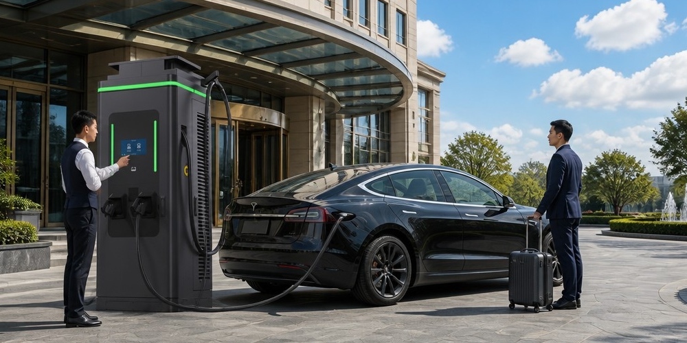
From a legal perspective, using a non-certified adapter often voids the vehicle’s warranty. If a fire occurs at a charging station due to a faulty adapter, the liability falls squarely on the user. Major standards bodies are now rushing to create certification programs for adapters (like UL 2251), but the market remains a “Wild West” for early adopters.
Chapter 12: Future Outlook: Megawatt Charging (MCS), V2X, and the Unified Convergence
As we look toward 2030, the CCS1 vs. CCS2 debate may be eclipsed by new technologies.
Megawatt Charging System (MCS)
For heavy-duty trucking, even 350 kW is too slow. The industry is developing MCS, which can deliver up to 3.75 Megawatts (3,000A at 1,250V). Interestingly, the MCS connector is a single global design, potentially ending the regional divide for the commercial sector.
Vehicle-to-Everything (V2X)
The integration of ISO 15118-20 will turn EVs into mobile power plants. Whether a car uses CCS2 or NACS, the ability to stabilize the grid during peak hours will be a key revenue stream for EV owners.
Conclusion
The divergence between CCS1 and CCS2 is a testament to the complexities of global standard-setting. While CCS2 has emerged as the clear winner in the international market, the rise of NACS has rewritten the rules for North America. For engineers and policy-makers, the lesson is clear: physical hardware is transient, but the underlying digital protocols (ISO 15118) and safety principles (IMD) are the true foundations of the electrified future. Understanding these technical nuances is essential for anyone navigating the high-voltage world of EV infrastructure.
Chapter 13: The Mathematics of Insulation Resistance: R_iso Calculations and Leakage Current
In the high-voltage (HV) domain of DC fast charging, the insulation resistance ($R_{iso}$) is not just a safety parameter but a measurable variable that dictates the operational status of the charging session. According to IEC 61851-23 and SAE J1772, the system must maintain a minimum insulation resistance to prevent hazardous leakage currents ($I_{leakage}$) that could flow through a human body in the event of a chassis fault.
The Measuring Principle
The Insulation Monitoring Device (IMD) typically uses a “switched resistor” or “pulse injection” method to measure the resistance between the DC conductors and the Protective Earth (PE). The total insulation resistance is defined as the parallel combination of the resistance from the positive line to ground ($R_p$) and the negative line to ground ($R_n$):
$$R_{iso} = \frac{R_p \cdot R_n}{R_p + R_n}$$
The safety requirement is generally set at 100 $\Omega/V$ for DC systems. For a vehicle charging at 800V, the minimum allowable $R_{iso}$ would be:
$$800V \times 100 \Omega/V = 80,000 \Omega = 80 k\Omega$$
Leakage Current Dynamics
Leakage current is a function of the system’s parasitic capacitance ($C_y$) and the insulation resistance. In a perfectly balanced system, $R_p = R_n$, and the voltage at the midpoint relative to ground is zero. However, if a fault occurs on the positive rail ($R_p \rightarrow 0$), the negative rail shifts to $-800V$ relative to the chassis. The IMD must detect this shift within milliseconds.
Table: Safety Thresholds for CCS1 vs. CCS2
| Parameter | CCS1 (Typical) | CCS2 (Typical) |
|---|---|---|
| Warning Threshold | 500 $\Omega/V$ | 500 $\Omega/V$ |
| Error/Shutdown Threshold | 100 $\Omega/V$ | 100 $\Omega/V$ |
| Max Response Time | < 10 seconds | < 10 seconds |
| Pre-charge Isolation Test | Mandatory | Mandatory |
Chapter 14: PLC Signal Integrity: Handling Noise in the 500kW Charging Environment
The Power Line Communication (PLC) used in CCS is based on the HomePlug Green PHY (HPGP) specification. While HPGP was originally designed for low-power smart home applications, its implementation in 500kW charging environments presents extreme electromagnetic compatibility (EMC) challenges.
The Noise Floor
High-power DC chargers utilize fast-switching Silicon Carbide (SiC) or Insulated Gate Bipolar Transistors (IGBTs) in their power stages. These components switch at frequencies ranging from 20 kHz to 100 kHz, creating significant harmonic noise. Since PLC operates in the 2 MHz to 30 MHz range, it is theoretically out of the band of the primary switching noise, but the high-frequency “ringing” and common-mode transients can easily saturate the PLC modem’s front-end.
Attenuation and Coupling
The Control Pilot (CP) signal is carried over an unshielded wire inside the charging cable. At 30 MHz, the cable acts as a complex transmission line with significant inductive and capacitive losses.
- CCS1 Cables: Longer, often heavier cables in the US can lead to higher signal attenuation.
- CCS2 Cables: In Europe, shorter cables at dense urban sites might suffer from cross-talk between adjacent dispensers.
To mitigate this, engineers use “Signal Injection Units” (SIUs) that utilize high-permeability ferrite cores to couple the PLC signal onto the CP line while blocking the 1 kHz PWM signal and high-frequency noise.
Chapter 15: ISO 15118-2 vs. -20: The Architectural Evolution of Message Sequences
The transition from the original ISO 15118-2 standard to the new ISO 15118-20 (often called “Dash 20″) represents the most significant software upgrade in the history of EV charging.
ISO 15118-2: The Foundation
The “-2″ version established the basic XML-based handshake:
- SupportedAppProtocol: Negotiates the version.
- SessionSetup: Establishes the connection.
- Identification: Handles RFID or Plug & Charge.
- ChargeParameterDiscovery: Exchanges battery limits.
- PowerDelivery: Controls the flow.
ISO 15118-20: The Future
Dash 20 introduces a completely new message structure designed for the next generation of energy services:
- Bi-Directional Support: Dedicated messages for V2G (Vehicle-to-Grid) and V2H (Vehicle-to-Home) discharging.
- Dynamic Mode: Allows the charger to tell the car to vary its current in real-time based on grid load, without restarting the session.
- Enhanced Security: Transitions from TLS 1.2 to TLS 1.3, providing faster handshakes and stronger encryption.
- Multiplexing: Allows multiple services (e.g., charging + data sync) to run over the same PLC connection.
Message Sequence Chart: Plug & Charge (PnC) vs. External Identification (EIM)
In PnC, the ContractSignatureCertChain is sent from the car to the charger. The charger verifies this against its backend OCSP (Online Certificate Status Protocol) server. In EIM, the user must present a physical card, and the charger sends an Authorize request to the backend. The latency of PnC is significantly lower, leading to a “Tesla-like” user experience.
Chapter 16: Thermal Engineering of High-Power Connectors: Materials, Contact Resistance, and Liquid Cooling
As we approach the limits of the CCS physical interface, thermal engineering becomes the primary design constraint.
Contact Resistance ($R_{contact}$)
The heat generated at the connector is defined by Joule’s Law: $P_{heat} = I^2 \cdot R_{contact}$. For a 500A charge:
- If $R_{contact} = 0.5 m\Omega$, $P_{heat} = 500^2 \cdot 0.0005 = 125 W$.
- If $R_{contact}$ degrades to $2.0 m\Omega$, $P_{heat} = 500^2 \cdot 0.002 = 500 W$.
500 Watts of heat in a confined plastic handle will lead to a catastrophic failure in minutes. This is why the silver-plating on the pins is critical. Silver has the lowest electrical resistance of any metal and provides a self-lubricating surface that reduces wear during thousands of mating cycles.
Liquid Cooling Systems
To handle currents above 350A, liquid cooling is mandatory. The system typically uses a closed-loop chiller unit inside the power cabinet.
- Coolant Type: Dielectric fluids are preferred to prevent short circuits in case of a leak, but water-glycol mixtures are more common due to their superior heat capacity.
- Hose Design: The DC+ and DC- conductors are hollow or surrounded by coolant channels. The “cold plate” is located directly behind the pins to wick heat away from the contact interface.
Chapter 17: Interoperability Case Studies: Debugging the Handshake between VW ID.4 and Electrify America Chargers
A famous example of CCS1 interoperability issues occurred in the early rollout of the VW ID.4 in the United States. Many owners reported “Red Ring” errors (charging failed) at Electrify America (EA) stations.
The Root Cause: Timing and XML
After months of data logging, engineers discovered a race condition in the SessionSetup phase. The EA charger (manufactured by a third party) was sending its SupportedAppProtocolRes faster than the ID.4′s onboard charger (OBC) software could initialize its IPv6 stack. The car would miss the message, time out, and abort the session.
The Fix: Software Buffering
The solution required a firmware update for both the car and the charger. The charger was modified to wait for an “ICMPv6 Neighbor Discovery” signal before sending the first PLC message, and the car’s timeout was extended from 2 seconds to 5 seconds. This case study highlights why “Testivals” are necessary but not sufficient; real-world environmental factors and network latency add layers of complexity that lab testing cannot fully replicate.
Chapter 18: Global Supply Chain Implications: Copper, Silver-Plating, and the Shortage of HPGP Chips
The manufacturing of CCS connectors is a highly specialized industry dominated by a few players like Phoenix Contact, Huber+Suhner, and TE Connectivity.
Raw Material Dependencies
- Copper: A single 350kW liquid-cooled cable can contain over 15kg of high-purity copper. The volatility of copper prices directly impacts the CAPEX of charging networks.
- Silver: The plating process for CCS2 pins requires precise electroplating techniques to ensure a uniform 5-10 micron layer. Any thinning leads to increased resistance and premature aging.
The HPGP Chipset Monopoly
The HPGP (HomePlug Green PHY) modem chips are the brain of every CCS vehicle and charger. For years, Qualcomm was the primary supplier (the QCA7000 series). During the global semiconductor shortage of 2021-2022, the lack of these chips stalled the production of thousands of charging stations. This has led to a push for secondary sourcing, with companies like Lumissil and Vertexcom entering the market, but the certification process for new silicon in the automotive sector is notoriously slow.
Chapter 19: Regulatory Frameworks: NEVI in the US vs. AFIR in the EU
Governments are no longer leaving standard adoption to the market.
EU: AFIR (Alternative Fuels Infrastructure Regulation)
The EU’s AFIR is the most aggressive mandate in the world. It requires:
- Fast chargers every 60km along major highways.
- CCS2 as the mandatory standard.
- Ad-hoc payment (credit card readers) to be integrated, moving away from closed RFID ecosystems.
US: NEVI (National Electric Vehicle Infrastructure)
The US Bipartisan Infrastructure Law allocated $5 billion for charging. The NEVI rules originally mandated CCS1. However, following the NACS pivot, the rules were amended to allow NACS cables as long as at least one CCS1 cable is present per site. This “Hybrid Model” is a temporary bridge as the US moves toward a full SAE J3400 future.
Chapter 20: The Convergence toward SAE J3400 (NACS) and its Impact on CCS1 Manufacturing
The shift to NACS (SAE J3400) in North America has fundamentally changed the roadmap for CCS1.
Manufacturing Pivot
Factories that were optimized for the bulky CCS1 handles are now being retooled for the smaller NACS design. The complexity of NACS lies in its “Dual Use” pins, which require high-speed DC switching contactors inside the car to switch between the AC onboard charger and the DC battery bus.
The Survival of CCS1
CCS1 will likely survive in South Korea and as a legacy standard in the US for the next decade. However, the R&D budget for CCS1 has effectively dropped to zero as the industry focuses on NACS and MCS. For global manufacturers, this means maintaining three separate product lines:
- CCS2: For the global market.
- NACS (J3400): For North America.
- MCS: For the global heavy-duty sector.
Chapter 21: Conclusion: The Unified Protocol in a Divided Physical World
As we have seen, the “Difference between CCS1 and CCS2″ is a tale of two physical manifestations of a single digital soul. Whether a vehicle uses the round CCS1 plug or the flat CCS2 plug, the underlying logic of ISO 15118, the safety of IMD monitoring, and the challenge of PLC signal integrity remain identical.
The charging standard war of the 2020s has taught us that interoperability is not just about the plug—it’s about the software, the grid, and the user experience. As the world converges toward a few dominant standards, the focus will shift from “Can I plug in?” to “How fast and smart is the charge?” The transition to NACS in the US and the solidification of CCS2 in Europe marks the end of the beginning for the EV revolution. The next decade will be defined by V2G, Megawatt speeds, and a truly seamless global charging network.
Chapter 22: Detailed Analysis of the Proximity Pilot (PP) and Control Pilot (CP) Circuit Diagrams
To truly appreciate the engineering behind CCS, one must examine the equivalent circuit of the pilot lines. These lines are the “nerves” of the charging system, ensuring that high voltage is never present on exposed pins and that the vehicle cannot drive away while connected.
The Control Pilot (CP) Circuit
The CP circuit is a 1 kHz, $\pm 12V$ signal generated by the EVSE. On the vehicle side, the circuit consists of a diode and a series of resistors ($R_1, R_2, R_3$) that the vehicle can switch into the circuit using transistors or relays.
- Diode Purpose: The diode ensures that only the positive part of the PWM signal is affected by the vehicle’s resistors. This allows the EVSE to detect a “short to ground” if the negative part of the PWM signal is unexpectedly affected by a fault in the vehicle’s resistor network—an essential safety check that prevents the EVSE from energizing a damaged cable or connector.
Reading the Duty Cycle
The EVSE encodes the available current in the PWM duty cycle of the 1kHz square wave, and the vehicle interprets it before closing the main contactors:
- 5% duty cycle: EVSE not ready—charging not allowed (used for status signaling).
- 10% duty cycle: EVSE ready, no ventilation required (the standard state for modern sealed DC systems).
- 16-85% duty cycle: The available current is proportional to the duty cycle—for example, 50% indicates a 50A limit, letting the vehicle’s onboard charger size its draw correctly.
- 90-97% duty cycle: Reserved for special states such as ventilation-required (legacy lead-acid) or specific DC signaling.
The beauty of the CP system is its fail-safe asymmetry: if the vehicle sees no valid square wave, it assumes the worst and refuses to charge; if the EVSE sees no valid response, it refuses to energize. Either side failing closed means a charging session cannot begin dangerously.
The Proximity Pilot (PP) Circuit
The PP circuit is the mechanical conscience of the connector. It uses a simple resistor to ground inside the plug to tell both sides whether a cable is fully inserted—and to prevent drive-away with a connected cable.
- Resistor Values: A 150Ω resistor indicates the cable is plugged into the vehicle but not locked; a 680Ω resistor indicates the cable is connected and locked; an open circuit (no resistor) means the connector is disconnected. The EVSE and vehicle read these values continuously.
- Drive-Away Protection: If the vehicle’s system detects the 150Ω state while the parking brake is released, it will not allow the gear to engage. If the cable is locked (680Ω), the vehicle will not allow the connector to release while charging current is flowing—eliminating the “yank out a live plug” hazard.
- Cable Presence Detection: On DC systems, the PP line also confirms that the charging cable is properly seated at both ends before the EVSE allows the high-voltage contactors to close.
Why Pilots Matter in the Real World
Together, the CP and PP circuits are why a charging session is safe even when a thousand amps are flowing. They are also the first place engineers look when a session fails to start: a corroded PP ground, a chipped CP resistor, or a damaged pilot pin accounts for a surprising share of “charger won’t start” service calls. Understanding these circuits turns a mysterious failure into a 10-minute diagnosis.
Key Takeaways
- The CP circuit carries a 1kHz PWM signal whose duty cycle encodes the available current; its diode-based design enables short-to-ground detection.
- The PP circuit uses a resistor network to detect cable presence and lock state, providing drive-away protection and connector-seat confirmation.
- Both circuits are fail-safe: a missing or invalid pilot signal aborts the session before any high-voltage contactor closes.
- Pilot-line faults are among the most common charger-start failures—a multimeter and this circuit knowledge solve most of them in minutes.
Contact MIDA Power engineers its CCS1/CCS2 chargers with pilot circuitry built for field diagnostics: clearly labeled test points, standardized fault codes, and service documentation that walks technicians through CP/PP troubleshooting. Contact us for technical documentation, training support, and product specifications.
Post time: Aug-09-2026
