
 Portable EV Charger
 Home EV Wallbox
 DC Charger Station
 BESS Charging Station
 V2G V2H V2V V2L
 EV Charging Module
 DC Charging Connector
 EV Accessories
How to use the Electric Bus Pantograph Up ?
Electric Bus Pantograph Up: Standard Operating Procedure (SOP)
The “Pantograph Up” charging system is a fully automated, hands-free solution. Drivers are not required to exit the vehicle or handle high-voltage cabling. Operations are conducted entirely from the cockpit via the onboard interface.The electric bus pantograph operates fully automatically and without human intervention. The driver does not need to leave the vehicle to plug or unplug the charging gun during the entire charging process; the entire process is automatically completed by the onboard system and the ground charging station.
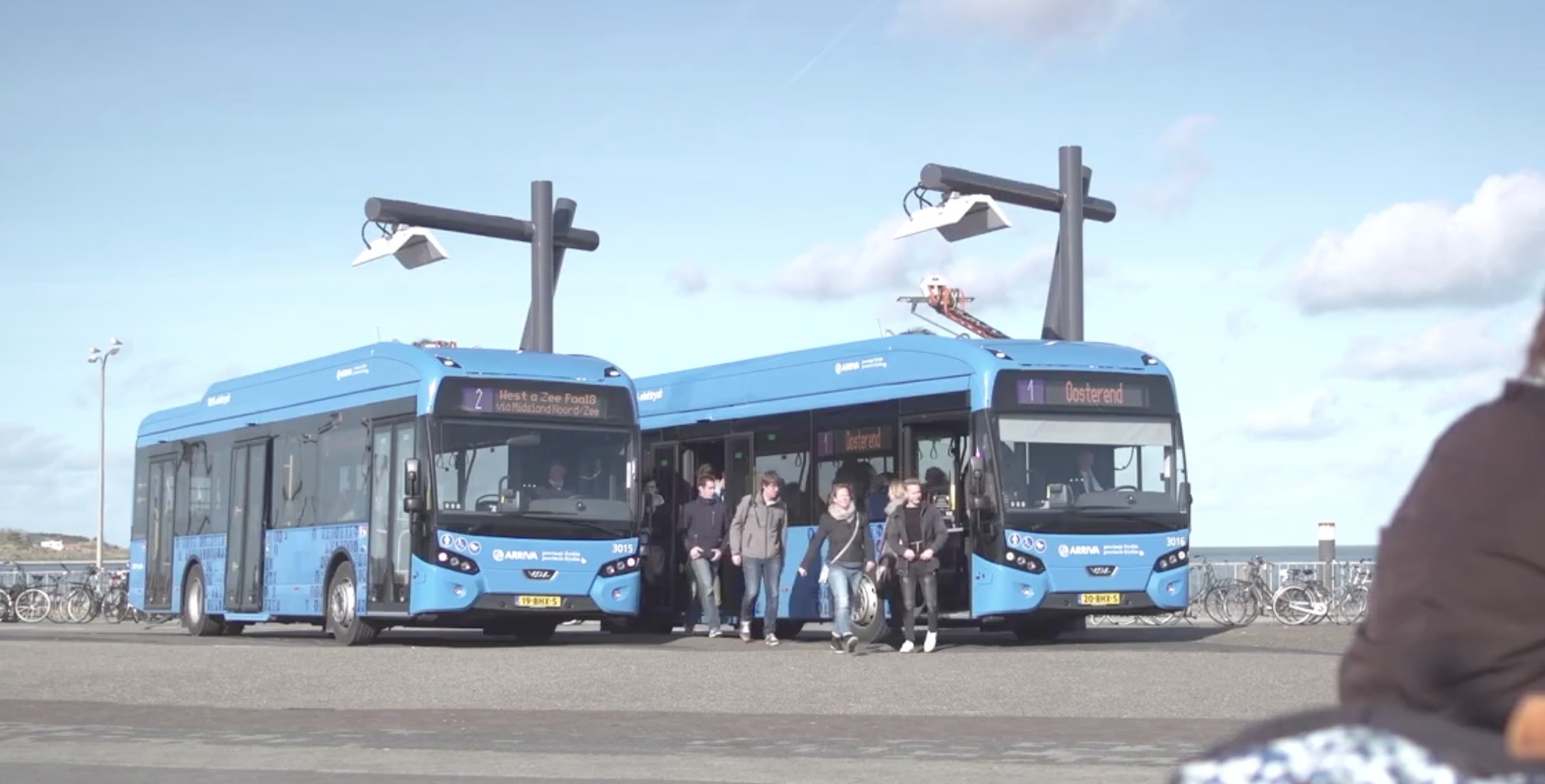
1. Precision Docking & Stationary Protocol
- Alignment: Approach the charging bay at low speed. Utilize ground markings or the overhead laser/camera docking guides located on the charging mast to align the vehicle.
- Positioning: Bring the bus to a full stop directly beneath the overhead charging hood. The typical docking tolerance is ±30 cm longitudinally (forward/backward) and ±10 cm laterally (sideways).
- Safety Interlock: Shift the transmission to Neutral (N) and engage the Parking Brake.
- Note: The charging system is interlocked with the vehicle’s braking system; deployment will be inhibited if the parking brake is not set or the vehicle remains in gear.
2. Deployment & Connection Initiation
- Wireless Handshake: Once the vehicle is stationary, the bus automatically establishes a secure communication link (Wi-Fi or RFID) with the charging infrastructure.
- Initiation: Activate the “Start Charge” or “Pantograph Up” command via the dashboard console or touchscreen.
- Status Monitoring: Monitor the instrument cluster for live feedback (e.g., “Pantograph Deploying”). The mechanical arm will unfold and extend to the overhead contact rails.
- Engagement: The carbon contact strips will seat firmly into the overhead hood, completing the high-power circuit.
3. Charging Management
- BMS Integration: The Battery Management System (BMS) performs a diagnostic handshake with the charger to synchronize voltage and current parameters.
- Power Transfer: High-capacity DC charging (typically 150kW to 600kW) commences automatically.
- Drive-Off Interlock: An active safety lockout remains in effect during charging. The vehicle’s traction system is disabled, preventing the bus from moving even if the accelerator is depressed, thereby protecting the overhead infrastructure.
4. Retraction & Departure
- Termination: Charging ceases automatically upon reaching the target State of Charge (SoC). To terminate early, select “Stop Charge” or “Pantograph Down” on the console.
- Stowage: The pantograph arm will retract and fold into its stowed position on the roof.
- Verification: Confirm the status indicator reads “Pantograph Stowed” or “Safe to Drive” before moving.
- Departure: Release the parking brake, select the appropriate gear, and exit the charging bay cautiously.
Operational Constraints & Safety Guidelines
- Infrastructure Clearance: Prior to deployment, verify that the path between the bus roof and the charging hood is clear of obstructions, such as low-hanging branches or debris.
- Mechanical Alerts: Do not attempt to move the vehicle if the dashboard indicates the pantograph is not fully seated in its stowed position.
- Environmental Factors: During extreme weather (freezing rain or ice storms), inspect the overhead rails for heavy ice accumulation. Excessive icing may impede the connection or cause electrical arcing.

Post time: Jul-11-2026
